CPLD (Complex Programmable Logic Device) is a complex user-programmable logic device due to the continuous connection structure. This structure is easy to predict the delay, so the circuit simulation is more accurate. CPLDs are standard LSI products that can be used in the design of various digital logic systems. In recent years, due to the adoption of advanced integration processes and mass production, the cost of CPLD devices has been declining, integration density, speed and performance have been greatly improved, and a complex digital circuit system can be realized with one chip; coupled with easy-to-use development tools. The use of CPLD devices can greatly shorten the product development cycle, which brings great convenience to design and modification [1]. This article takes ALTERA's MAX7000 series as an example to realize parallel communication between MCS51 microcontroller and PC104 ISA bus. With this communication method, the data transmission is accurate and high-speed. In the data acquisition system controlled by the MCS51 single-chip microcomputer of 12 MHz crystal oscillator, the real-time communication with the PC104 ISA bus interface can be met, and the communication speed is up to 200 Kbps. 1 system overall design This system uses CLPD to realize parallel communication between the microcontroller and the PC104 ISA bus interface. Because PC104 mainly completes other aspects of data collection, it only needs to receive the data sent by the MCU when it is idle. Therefore, the real-time communication between the two parties is required to be strong, but the amount of data is not very large. Therefore, in the system design, the single chip interrupt mode receives the data, and the PC 104 receives the data by using the query mode. The system design scheme is shown in Figure 1. In the MCU part of Figure 1, D[0..7] is the data bus, A[0..15] is the address bus, RD and WR are the read/write signal lines, and INT0 is the external interrupt of the MCU. When the external interrupt signal of the microcontroller is valid, the microcontroller receives the data. In the CPLD part, it is implemented by a piece of EPM7128LSC84 in the MAX7000 series to complete data transmission, status inquiry and delay waiting between MCS51 and PC104 ISA bus interface. In the ISA part of PC104, only the 8-bit data bus D[0..7] of ISA is used, A[0..9] is the address bus of PC104; IOW and IOR are read/write signals to the specified device; AEN is allowed DMA control address bus, data bus and read and write command lines for DMA transfer, and read and write to memory and I / O devices; IOCRYY is I / O ready signal, I / O channel ready high, then the processor generated The memory read/write cycle is 4 clock cycles, and the generated I/O read/write cycle and DMA byte transfer take 5 clock cycles. The MCS51 sets the signal low to make the CPU insert the wait cycle, thus extending I / O cycle; SYSCLK is the system clock signal for synchronization with external devices; RESETDR is the power-on reset or system initialization logic, which is the system total clear signal.
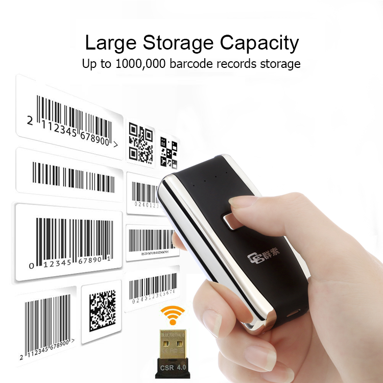
Qunsuo have more than 15 years experience in proving Barcode Scanner . We provide 1D Barcode Scanner and Qr Code Scanner , help customers from various industries. All of our barcode scanner support connecting with Android IOS via bluetooth. Furthermore, Our barcode scanner also support connecting with PC via 2.4G wireless module. Qunsuo provide portable scanner, Finger Barcode Scanner and Handheld Barcode Scanner. If any interests, please feel free to send inquiry to us for more information.
Mini Qr Code Scanner,Micro Usb Barcode Scanner,Mini Usb Barcode Scanner,Ipad Mini Barcode Scanner Shenzhen Qunsuo Technology Co., Ltd , https://www.qsprinter.com