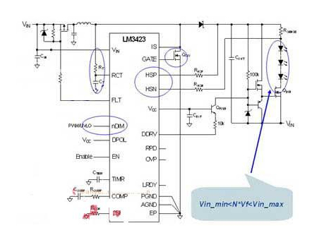
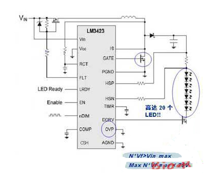
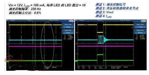
In recent years, exterior lighting, such as daytime running lights (DRL), and headlights have begun to switch to LED bulbs. It is expected that car headlights will soon switch to high-brightness LED lights. In addition, inside the body, the backlight of some in-car displays has also begun to use LEDs as light sources, such as instrument panels and TFT displays. Brake lights, turn signals, reversing lights and rear fog lamps have been used as light sources for 21W to 27W and 280 to 570 lumens. The taillights, parking lights, car side lights and turn signal flashes use 4W to 10W tungsten lamps with a brightness of 40 to 130 lumens, while the car headlights use a high-intensity xenon fluorescent tube (HID). However, in automotive lighting, LEDs are increasingly used as light sources. The tail center high position brake light is the first car light to adopt LED. In addition, in the lamp market, other exterior lighting and indicators such as brake lights, turn signals and interior lights have been converted to LED bulbs. In recent years, exterior lighting, such as daytime running lights (DRL), and headlights, have begun to switch to LED bulbs. It is expected that car headlights will soon switch to high-brightness LED lights. In addition, inside the body, the backlight of some in-car displays has also begun to use LEDs as light sources, such as instrument panels and TFT displays. Advantages of automotive LED lighting systems White LEDs have a color temperature of approximately 6000K and are visually equivalent to natural light. The ability to distinguish colors by the human eye is best under natural background conditions. In the evening, the human eye only has a good ability to distinguish between the scene or the edge of the road in the natural color. The average life of LED lamps is longer than that of tungsten lamps and high-intensity fluorescent tubes, and it is more stable and reliable. If you can reduce the chance of failure, and do not need to change the bulb frequently, it saves a lot of trouble. And using LEDs can save more energy. LED lights are smaller and easier to fit into the lamp holder, making it easier to work with stylish lighting designs while taking up less space. More importantly, LED brake lights start faster. The LED brake light has a lighting time of only about 50ms, which is about 250ms faster than the start time of the tungsten bulb, thus reducing the risk of collision with the trailing vehicle. In addition, LEDs are solid-state light sources that can withstand greater vibration. Technical requirements for driving LED lights Since the brightness of the LED is proportional to the current flowing through it, a constant current source is required to drive the LED. In any case, the current flowing through the LED should be kept constant to ensure the brightness of the LED. It is also necessary to control the ripple current to an acceptable level under any circumstances. Therefore, the design of the LED driver belongs to the power conversion circuit design, which is characterized by a constant current output instead of a constant voltage output. In LED driver designs, blocking circuits must be added to protect against reverse power operation. Another challenge we will encounter is to ensure that the LEDs work properly in the event of a cold start or load outage. In normal operation, the car's battery supply voltage is between 9V and 16V (for example, 12V system bus), while the large truck's battery supply voltage is between 18V and 32V (for example, 24V system bus). In the event of a load outage or cold start, the battery's input voltage range will vary greatly from the normal range. During the operation of the generator, if the power supply of the battery is suddenly cut off, the generator will continue to generate electricity at this time, and the power consumption of the capacitor-powered part will suddenly increase. If no protective measures are taken, it will be damaged. Electrical appliances. If the LED driver is not driven by a constant current, the current of the LED will change, causing the brightness of the LED to change, which is why the current car light will flicker. The following is a definition of a load power-down test that mimics some cases of load breaks. Different car manufacturers use different standards, so the definition of load power-off test is also different. Figure 1 is only one case. Definition of load power failure test   Although the load dump causes an increase in the load voltage, most advanced alternators are equipped with a centrally controlled load-carrying clamp circuit. The reference level of the 12V bus system is limited to between 35V and 42V, while the reference level of the 24V bus system is clamped between 50V and 60V. In cold weather, the starter device will cause the battery supply voltage to drop significantly. Figure 2 shows the typical waveform of the "cold start" test. Figure 2 Typical waveform of the "Cold Start" test Since the input supply end of the LED driver is connected to the input of the battery, a car light such as a brake lamp that is safe for driving must be unaffected by load power interruption and cold start, and must even be able to continue normal operation in this case. In a typical case, the input range of the 12V bus system is 6V to 42V, and the input voltage range of the 24V bus system is 12V to 60V. LED drive technology Resistor current limiting is one of the LED driving methods, which has the advantages of low cost and simple design. The disadvantage is that the current will change with the forward voltage and the driving voltage, so the brightness emitted by the LED will change. When the battery voltage is relatively high, the efficiency of the drive is very poor, because most of the power is consumed at this time. In addition, the current limiting resistor generates a large amount of heat, causing heat dissipation problems. So this is a simple but not the most efficient method. The second method is a linear current regulator, also called a constant current source. Its advantages are simple design and constant current; the disadvantage is that the efficiency is very low, and as the input voltage increases, the voltage drop carried by the linear chip is larger, so the linear chip also generates a large amount of heat. However, it improves the shortcomings of current fluctuations in the resistor current limiting method. In addition to the above two methods, there is also a switching power supply type driving method. Table 1 compares the three different methods. The switching power supply is used as the LED driving method with high efficiency and constant current. Because of the high efficiency of the open-light power converter, it is used by more and more car manufacturers. The biggest drawback is that the design line is more complicated and the cost is relatively high. Comparison of three LED driving methods Table 1 Comparison of three LED driving methods Why use a boost/buck LED driver in automotive lighting? This is because the battery voltage is fluctuating. When the voltage fluctuates, we need to keep the current flowing through the LED constant. The step-up/step-down LED driver ensures that the current remains constant regardless of whether the input voltage is higher or lower than the output voltage. This ensures that the safety-related lighting can maintain a constant brightness during load power outages and cold starts. In addition, diverse LED automotive lighting applications require different LED driver topologies. Some automotive lamp manufacturers hope to have an LED drive platform that can be adapted to different LED configurations for different lighting systems. The boost/buck LED driver is the ideal driver solution for most high-brightness automotive lighting systems. The LM3423 (Figure 3) is a step-up/step-down LED driver IC from NS that provides fast dimming control, reliable protection and fault display, as well as boost, floating buck and floating. Boost/buck LED drivers meet the requirements of different LED in-vehicle drivers. Figure 3 LM3423 boost / buck application schematic Boost LED driver for LED backlight systems In general applications, we use a boosted constant current LED driver to drive multiple strings of LEDs. This configuration of LED backlight system provides backlighting for automotive dashboards and navigation system displays. In addition, the car dashboard display must be equipped with dimming control to control the brightness of the LED backlight. If the ambient light is brighter, the brightness can be increased, and when the surrounding environment is dark, the brightness can be lowered to prevent the driver's eyes from adapting to the sharp brightness transition and affecting driving safety. In addition, controllers with PWM dimming must have good contrast, which is a good linearity adjustment. The PWM signal is a serial pulse signal. We can control the emission of the pulse by switching the current switch, so that the LED emits a flash of more than 100 Hz. So we visually think that the brightness has been reduced because the human eye will filter/average the brightness. The dimming function is achieved by the duty cycle of the dimming. If the duty cycle of the device is small, the dimming range will be larger and have better linearity. There are usually two methods: one is analog signal dimming, and the other is PWM signal dimming. Since analog dimming is achieved by changing the current of the LED, the color of the LED changes when the current of the LED changes, so we usually use PWM dimming as the brightness control method. With this method, the LED is either turned on or off, and does not change the color of the LED. The LM3423 supports fast dimming control and a “0†shutdown current function for automotive navigation system displays and instrument panel LED backlighting systems (Figure 4). It ensures that the current flowing through each lamp is consistent, and a MOS tube is connected in series below the LED as a dimming control switch. Among them, the nDIM pin is responsible for performing input undervoltage lockout and PWM dimming. Whenever a PWM signal is input, the DDRV pin drives the DIM N-FET, commanding the LEDs in series to switch quickly to control the brightness, and the dimming control frequency can be as high as 50 kHz. Figure 4 LM3423 boost LED driver Figure 5 shows a comparison of dimming effects. It can be seen that at very low duty cycles, the same switch can be maintained and the current flowing through the LED is constant. The dimming duty ratio shown in the figure is 0.5%, the input voltage is 12V, the current of the LED is 100mA, and the number of driving is 10 LEDs per string. The dimming frequency here is 230Hz, when the brightness of the surrounding environment changes. In the dark, the LED backlight of the car display will reduce the brightness of the light. If the duty cycle is small, the brightness can be adjusted very low. When the ambient brightness is very dark, the brightness of the instrument panel will not be dazzling. Figure 5 LM3423 dimming control effect comparison When using a conventional boost mode driver, there is a problem: no matter whether the controller driver works or not, there is a path between the input and the output. In this case, the battery at the input will have a DC path to the load. Causes leakage. When used in car lighting, the car will discharge the battery when it is not used for a long time. When you start the vehicle again, you will find that the battery is dead. Another problem is that the battery is discharged when there is a short circuit at the output. Even if the main switch is turned off, it will not affect the leakage of the output. In this case, a fuse is added to the output to prevent a short circuit. The LM3423 can solve this problem and effectively extend the battery life. If the LED string is connected to ground, a short circuit is formed, and the input P-FET driven by the FLT pin is turned off, thereby making the input path an open circuit and avoiding leakage problems.
PCB
Connectors: Backplane, Wire-to-Board, Board-to-Board Connectors
These types of connector systems are
mounted or processed to a printed circuit board (PCB). There are a variety of PCB connectors and accessories best designed for specific uses. To name some, they include: Din41612 Connector ,Board To Board Connectors,Battery Holders Clips Contacts, Future Bus Connectors , PLCC Connectors .
Din41612 Connector
Board To Board Connectors
Battery Holders Clips Contacts
Future Bus Connectors
PLCC Connectors
1.ANTENK manufactures a wide range of application specific board stacking PCB connectors which were designed and built to specific customer requirements. Our experienced staff has developed custom products in a variety of contact styles, pitches and stacking heights. Our designs range from new concepts to duplicating existing market products identically or with improvements. Many desigsn are produced using automated manufacturing processes to increase reliability and provide significant cost savings.
2.Our products are widely used in electronic equipments,such as monitors ,electronic instruments,computer motherboards,program-controlled switchboards,LED,digital cameras,MP4 players,a variety of removable storage disks,cordless telephones,walkie-talkies,mobile phones,digital home appliances and electronic toys,high-speed train,aviation,communication station,Military and so on
What is a Pcb Connector ?
Other names for PCB Connectors
PCB Connectors can be known as PCB Interconnect product. Specific terms are also used for the two sides of the connection. Male PCB Connectors are often referred to as Pin Headers, as they are simply rows of pins. Female PCB Connectors can be called Sockets, Receptacles, or even (somewhat confusingly) Header Receptacles.
Din41612 Connector,Board To Board Connectors,Battery Holders Clips Contacts,Future Bus Connectors,PLCC Connectors ShenZhen Antenk Electronics Co,Ltd , https://www.antenk.com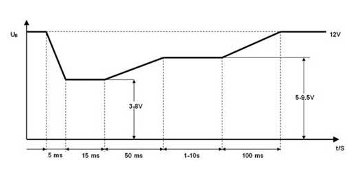


Printed Circuit Board Connectors are connection systems mounted on PCBs. Typically PCB Connectors are used to transfer signals or power from one PCB to another, or to or from the PCB from another source in the equipment build. They provide an easy method of Design for Manufacture, as the PCBs are not hard-wired to each other and can be assembled later in a production process.
PCB Connector orientations
The term PCB Connector refers to a basic multipin connection system, typically in a rectangular layout. A mating pair of PCB Connectors will either be for board-to-board or cable-to-board (wire-to-board). The board-to-board layouts can give a range of PCB connection orientations, all based on 90 degree increments:
Parallel or mezzanine – both connectors are vertical orientation;
90 Degree, Right Angle, Motherboard to Daughterboard – one connector is vertical, one horizontal;
180 Degree, Coplanar, Edge-to-Edge – both connectors are horizontal orientation.
Application design of automotive LED lighting system
2 times
Window._bd_share_config = { "common": { "bdSnsKey": {}, "bdText": "", "bdMini": "2", "bdMiniList": false, "bdPic": "", "bdStyle": " 0", "bdSize": "24" }, "share": {}, "image": { "viewList": ["qzone", "tsina", "tqq", "renren", "weixin"], "viewText": "Share to:", "viewSize": "16" }, "selectShare": { "bdContainerClass": null, "bdSelectMiniList": ["qzone", "tsina", "tqq", "renren" , "weixin"] } }; with (document) 0[(getElementsByTagName('head')[0] || body).appendChild(createElement('script')).src = 'http://bdimg.share. Baidu.com/static/api/js/share.js?v=89860593.js?cdnversion=' + ~(-new Date() / 36e5)];