10-25HP Compressor Series Sealed Terminal Blocks 10-25Hp Compressor Series Sealed Terminal Blocks,Compressor Sealing Terminal Three-Phase Socket,Air Conditioner Compressor Three-Phase Socket,Air Conditioning Compressor Seal Terminal Shenzhen Capitol Micro-Electronics Co.,LTD , https://www.capitolgtms.com
An important analytical method for motor vector control
In the operation of an electric motor, a rotating coordinate system that rotates at the same speed as the motor's magnetic field is established. This system is commonly known as the DQ (Direct-Quadrature) rotating coordinate system. In this frame of reference, all electrical signals can be represented as constant values, simplifying the analysis and control of the motor. A key question arises: can the results of the DQ transformation be directly obtained using measuring instruments?
The DQ transformation is a decoupling technique that converts the three-phase windings of an induction motor into an equivalent two-phase system. It transforms the rotating reference frame into a stationary orthogonal one, allowing the voltage and current to be expressed in terms of direct current components. This transformation enables independent control of each variable, reducing the effects of harmonic and unbalanced voltages. Moreover, due to the use of synchronous rotation, it becomes easier to separate fundamental wave components from harmonics.
In DC motors, the main magnetic flux is primarily determined by the field winding's excitation current, which is why their mathematical models and control systems are relatively simple. If the physical model of an AC motor could be transformed into a DC-like structure, analysis and control would become significantly easier. This idea forms the basis for coordinate transformations used in modern motor control.
Three-phase symmetrical windings A, B, and C, when supplied with balanced sinusoidal currents, generate a rotating magnetomotive force F that rotates at the same angular frequency as the current. This spatially sinusoidal force moves along the phase sequence of ABC, creating a rotating magnetic field. The figure below illustrates this concept.
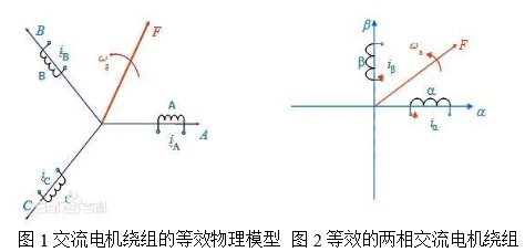
A rotating magnetomotive force does not have to be limited to three-phase systems. Any symmetrical multi-phase winding—such as two-phase, four-phase, or more—can produce a rotating magnetic field if fed with balanced currents. Among these, the two-phase system is the simplest. Figure 2 shows two-phase windings a and b, which are 90° out of phase, and when supplied with a 90° time-shifted AC current, they also generate a rotating magnetomotive force F.
When the magnitude and rotational speed of the magnetomotive forces in Figures 1 and 2 are equal, the two-phase winding is considered equivalent to the three-phase one. Figure 3 presents two perpendicular windings, d and q, carrying DC currents id and iq. These create a fixed magnetomotive force relative to the windings. If the entire core, including these windings, rotates at synchronous speed, the magnetomotive force naturally becomes a rotating one. By matching its magnitude and speed to those in previous figures, the rotating DC winding becomes equivalent to the fixed AC windings.
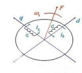
It becomes clear that the three-phase AC windings in Figure 1, the two-phase AC windings in Figure 2, and the rotating DC windings in Figure 3 are equivalent under the same rotating magnetomotive force condition. Therefore, the currents iA, iB, iC in the three-phase system, ia, ib in the two-phase system, and id, iq in the rotating DC system are all equivalent, producing the same rotating magnetomotive force.
**Application of DQ Coordinate Transformation**
The theory of motor coordinate transformation has been widely applied in electrical engineering. Beyond motor control and transient analysis, it is also used in power system fault detection, grid power quality monitoring, and more. Key applications include:
1. Motor control
2. Analysis of transient motor operations
3. Motor fault diagnosis
**Test Methods**
DQ transformation is extensively used in motor testing. With accurate rotor position information and precise measurement of three-phase currents, real-time processing can be achieved using high-speed FPGA technology. Through a Clark transform, the three-phase stationary stator windings are converted into a two-phase stationary system, producing Iα and Iβ outputs. Then, a Park transform is used to convert this into a two-phase system aligned with the rotor, yielding ID and IQ values. The motor control process involves reversing this transformation: setting the excitation and torque currents, converting them back to the stator-fixed two-phase system, and then to the three-phase system for control.
Currently, ZLG Zhiyuan Electronics is planning to integrate DQ transformation into their power analyzers, providing valuable insights for motor control design. By comparing setpoints with test results from the analyzer, engineers can optimize algorithms and improve control performance.
(Source: ZLG Zhiyuan Electronics)