Microcomputer Integrated Measurement And Control Device Measurement And Control Device,Microcomputer Protector,Bus Comprehensive Protection Measurement,Pt Parallel Device zhejiangjinyidianqiyouxiangongsi , https://www.jooeei.com
Analysis of DSP for Floating Point Fast Fourier Transform
**Foreword**
This paper aims to demonstrate the use of the internal DSP capabilities of the STM32F30x microcontroller for performing a floating-point Fast Fourier Transform (FFT). In practical applications, an ADC is used to sample signals generated by a waveform generator. These sampled data are then processed using FFT, and the results are compared with those obtained from MATLAB simulations to evaluate accuracy. The implementation utilizes the ARM DSP library, along with the floating-point unit and DSP instructions available on the STM32F30x.
**Simulate ADC Sample Data to Implement FFT**
**Generate AM Modulated Waveforms Using MATLAB**
The waveform formula is given as:
**AM_50 = sin(2πfc) × (1 + 50% × sin(2πfm))**, where **fc** is the carrier frequency, **fm** is the modulation frequency, and the modulation depth is 50%. To make it suitable for ADC sampling, the waveform is offset by 1.5V. The final expanded formula becomes:
**AM_50 = [sin(2πfc) + 50% × sin(2πfm)] × sin(2πfc) + 1.5**
**MATLAB Code:**
```matlab
x = sin(2*pi*fm*t); % Modulation wave
figure; plot(t,x);
y = sin(2*pi*fc*t); % Carrier wave
figure; plot(t,y);
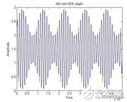
z1 = y.*(1 + m1*x) + 1.5; % AM Wave with 50% depth
figure; plot(t,z1);
xlabel('Time'); ylabel('Amplitude'); title('AM with 50% depth');
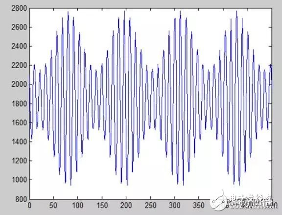
Z1 = z1 * 4096 / 3.3; % Convert to 12-bit ADC value
```
The resulting waveform is shown in Figure [1].
**Generate Analog ADC Data and Perform FFT Using STM32F30x**
The generated data is stored in the `AM_50_ADC_Data[]` array. Real numbers are converted into complex numbers, and a 1024-point FFT is performed using the `arm_cfft_f32` function from the ARM CMSIS-DSP library.
```c
/* Convert real data to complex format */
for(i=0; i < fftSize; i++) {
testInput_f32_10khz[i*2+1] = 0;
testInput_f32_10khz[i*2] = AM_50_ADC_Data[i];
}
/* Process the data through the CFFT/CIFFT module */
arm_cfft_f32(&arm_cfft_sR_f32_len1024, testInput_f32_10khz, ifftFlag, doBitReverse);
/* Compute the magnitude of each bin */
arm_cmplx_mag_f32(testInput_f32_10khz, testOutput, fftSize);
```
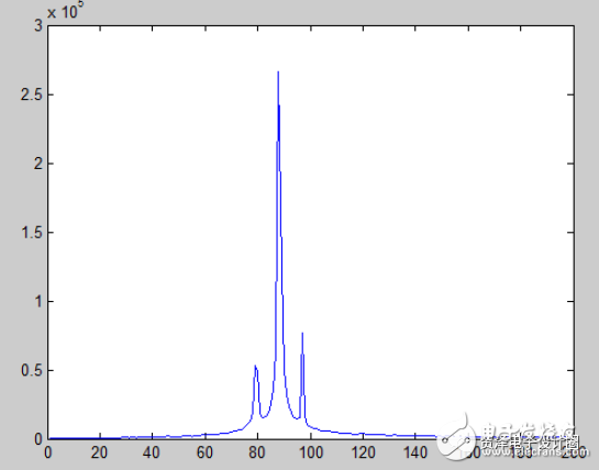
The results are printed and compared with MATLAB calculations. For display purposes, only the integer parts are compared. Figure [2] shows the MATLAB output, while Figure [3] displays the result from the STM32F30x.
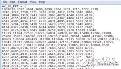
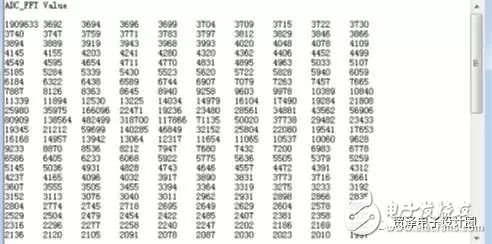
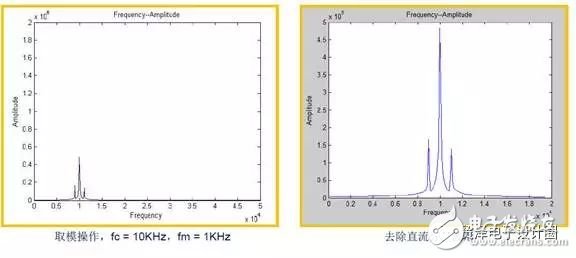
From a data perspective, the FFT results from both MATLAB and the STM32F30x are highly consistent, confirming that the data can be directly used. Based on time-domain to frequency-domain conversion, theoretically, the DC component, the carrier frequency **fc**, and the sidebands **fc ± fm** should show peaks. The actual FFT output matches this expectation.
**Actual ADC Sampling and FFT Operation**
An arbitrary waveform generator is used to produce a 50% amplitude-modulated signal with a carrier frequency of 10 kHz, a modulating frequency of 1 kHz, and an offset of 1.5 V.
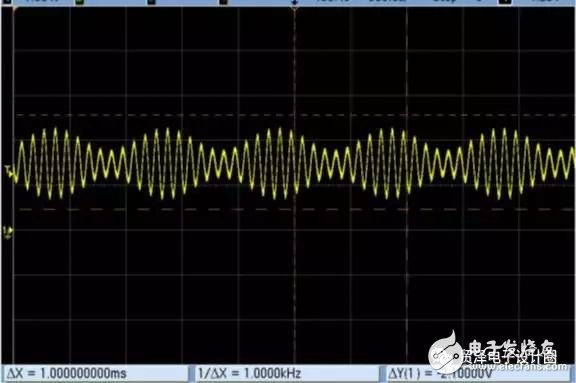
The STM32F30x performs ADC sampling, and the results are stored in an array. When imported into MATLAB, the waveforms match the expected shape.
The FFT of the ADC samples is then computed, and the frequency spectrum is analyzed.
**Conclusion**
The ADC-sampled waveform from the STM32F30x can be fully processed using FFT, and the results align well with theoretical expectations. The floating-point unit and built-in DSP features of the STM32F30x allow for fast and efficient signal processing, making it a powerful tool for real-world applications.