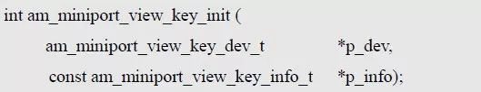
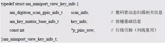
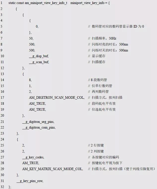
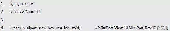
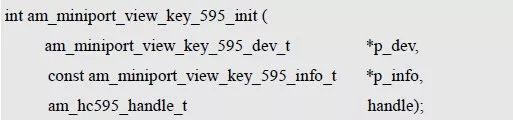
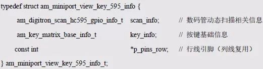
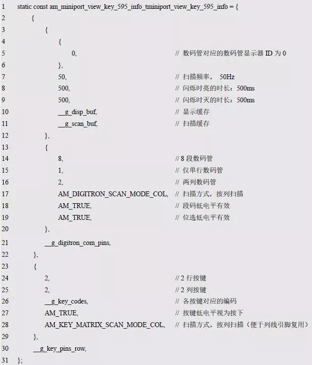
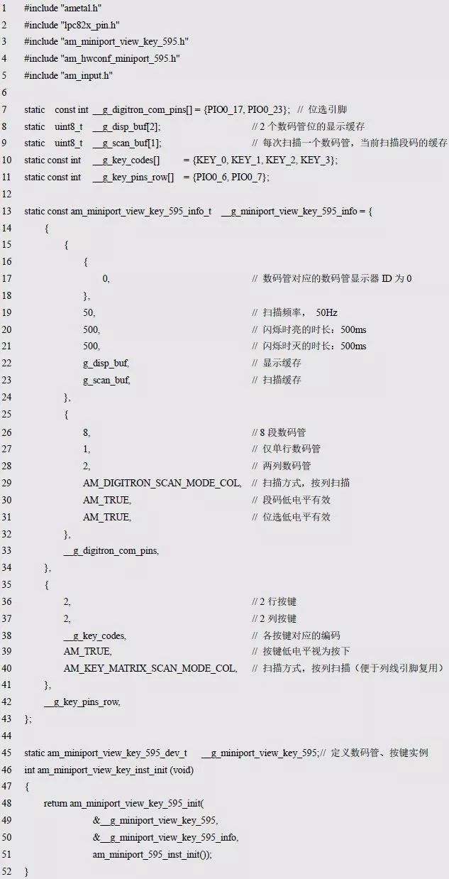
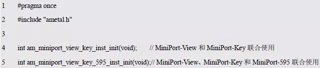
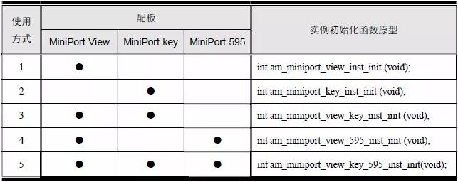
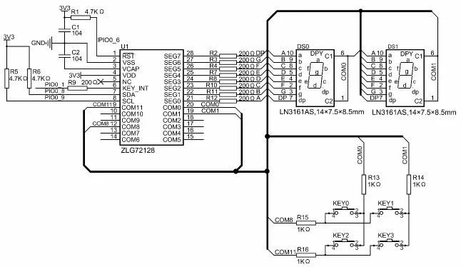
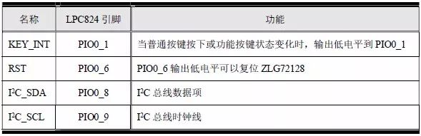
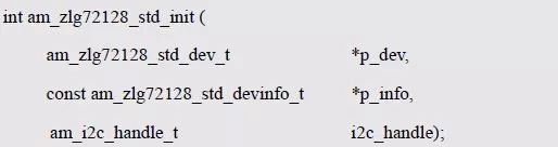
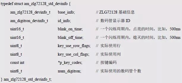
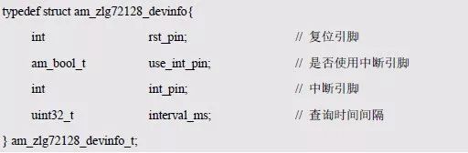
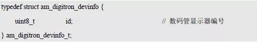
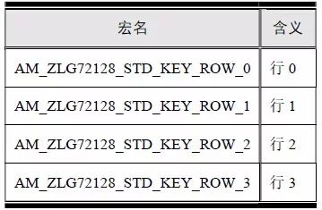
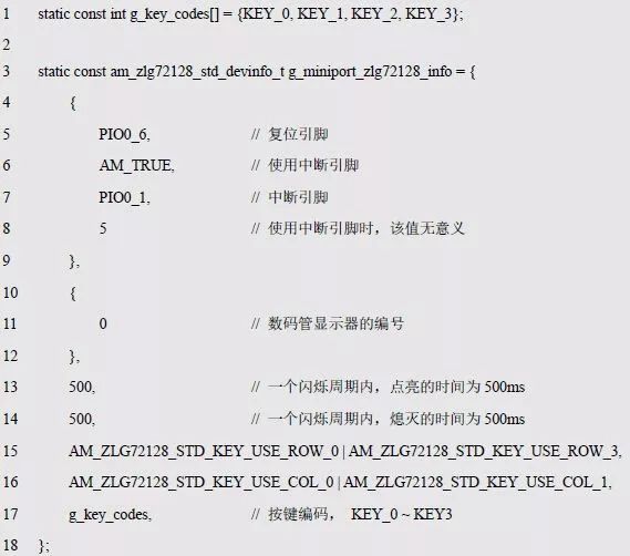
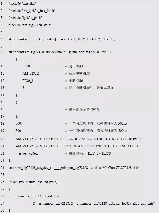
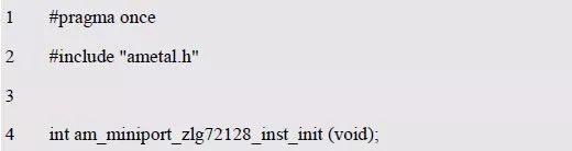
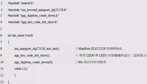
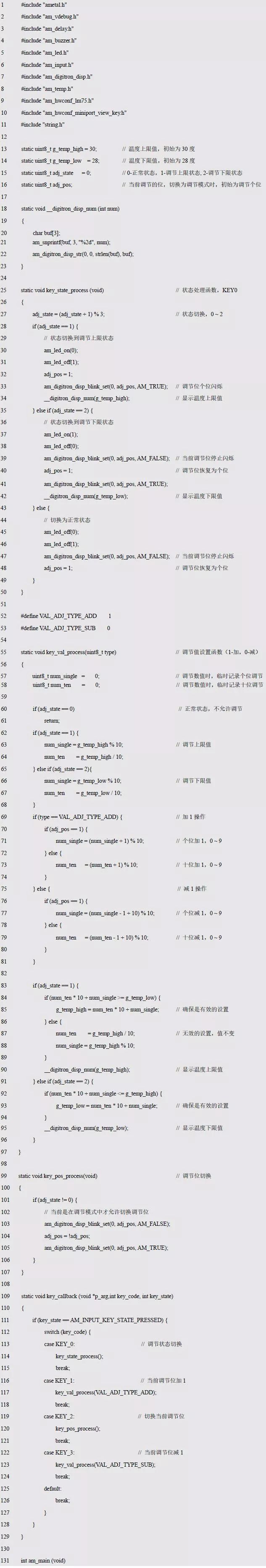
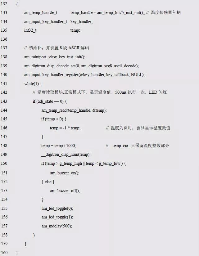
Prof. Zhou Ligong’s new book, "Programming for AMetal Frameworks and Interfaces (Part 1)," provides an in-depth exploration of the AMetal framework. By studying this book, readers can gain insights into highly multiplexed software design principles and development methodologies for interface programming. The focus is on refining your own core domain, shifting your programming mindset, and achieving mutual growth between the company and the individual. The seventh chapter covers general-purpose interface programming. It includes topics such as 7.7 combining a digital tube with a matrix keyboard, 7.8 ZLG72128 - managing digital tubes and keyboards, and 7.9 thermostat implementation. 7.7 Digital Tube Combined with Matrix Keyboard The bit selection pins of the digital tube are PIO0_17 and PIO0_23, while the column line pins of the matrix keyboard also use these same pins. When both components are used together, their pins are shared, which is a common hardware design that helps save I/O resources. AMetal offers a driver that combines a digital tube and a matrix keyboard. This driver essentially integrates the digital tube driver and the matrix keyboard driver, avoiding redundancy by not repeating the same information multiple times, such as the bit selection pin used in the digital tube instance. This approach ensures consistency and efficiency in the code. There are two types of digital tube drivers: one using GPIO to output segment codes, suitable for MiniPort-View; and another using HC595 to output segment codes, corresponding to MiniPort-View + MiniPort-595. When combined with a matrix keyboard, there are two scenarios: the first involves a GPIO-based digital tube with a matrix keyboard (MiniPort-View + MiniPort-Key), and the second uses an HC595-based digital tube with a matrix keyboard (MiniPort-View + MiniPort-595 + MiniPort-Key). > > > 7.7.1 Digital Tube, Keyboard, and I/O Driver When using MiniPort-View and MiniPort-Key together, the corresponding driver initialization function (am_miniport_view_key.h) is as follows: P_dev is a pointer to an instance of type am_miniport_view_key_dev_t, and P_info is a pointer to the instance information of type am_miniport_view_key_info_t. Instance The am_miniport_view_key_dev_t type (am_miniport_view_key.h) is defined as follows: Here, miniport_view_key is a user-defined instance whose address is passed to p_dev. 2. Instance Information The definition of the type of instance information associated with the digital tube, matrix keyboard, and am_miniport_view_key_info_t (am_miniport_view_key.h) is as follows: Scan_info is the digital tube instance information of type am_digitron_scan_gpio_info_t (for GPIO output segment code), and its definition is related only to the digital tube. Key_info is the basic information of the matrix keyboard of type am_key_matrix_base_info_t. When the digital tube and matrix keyboard are used together, the column line pins of the matrix keyboard are the same as the bit selection pins of the digital tube. Therefore, it's no longer necessary to specify the column line pins of the matrix keyboard. Instead, only the row line pins are specified using p_pins_row. Based on this, you can define the instance information for the MiniPort-View + MiniPort-Key device as follows: Based on the instance and instance information, the initialization of the digital tube instance can be completed: This will initialize both the digital tube and the buttons simultaneously. Once initialized, you can operate the digital tube and buttons using the universal digital tube interface and the universal button interface. Based on modular programming, the definitions of initialization-related instances and instance information are stored in the configuration file of the digital tube. For details, see Listing 7.25 and Listing 7.56. Listing 7.25 Digital tube, button joint use instance initialization function implementation (am_hwconf_miniport_view_key.c) Listing 7.56 Digital tube, button joint use instance initialization function declaration (am_hwconf_miniport_view_key.h) Afterward, you can simply call the parameterless instance initialization function to complete the initialization of the MiniPort-View + MiniPort-Key instance: Once the initialization is complete, you can operate the digital tube and buttons using the universal digital tube and button interfaces. > > > 7.7.2 Digital Tube, Keyboard, and HC595 Driver When using MiniPort-View, MiniPort-Key, and MiniPort-595 together, the corresponding driver initialization function prototype (am_miniport_view_key_595.h) is as follows: P_dev is a pointer to an instance of type am_miniport_view_key_595_dev_t, and P_info is a pointer to the instance information of type am_miniport_view_key_595_info_t. Instance The am_miniport_view_key_595_dev_t type (am_miniport_view_key_595.h) is defined as follows: Here, miniport_view_key_595 is a user-defined instance whose address is passed to p_dev. 2. Instance Information The definition of the type am_miniport_view_key_595_info_t (am_miniport_view_key_595.h) describing the instance information associated with the digital tube and matrix keyboard is as follows: The only difference is that the scan_info member of the digital tube information has changed from am_digitron_scan_gpio_info_t to am_digitron_scan_hc595_gpio_info_t, while the rest remains unchanged. Since the hardware difference is only in the output method (GPIO vs. HC595), the instance information is slightly different in the digital tube section. The instance information for the MiniPort-View + MiniPort-Key + MiniPort-595 device is defined as follows: 3. HC595 Handle If you use the MiniPort-595 to output segment codes, you should obtain the HC595 handle through the MiniPort-595 instance initialization function, which is: The obtained HC595 handle can be directly passed as an argument to the handle. The initialization of the MiniPort-View + MiniPort-Key + MiniPort-595 device instance can be completed based on the instance, instance information, and HC595 handle, such as: Once initialized, you can use the universal digital tube and button interface to operate the digital tube and buttons. Based on the modular programming idea, the definitions of initialization-related instances and instance information are stored in the configuration file of the digital tube, and the relevant content is added to the am_hwconf_miniport_view_key.c file. At the same time, the declaration of the instance initialization function is added to the am_hwconf_miniport_view_key.h file, as shown in Listing 7.57 and Listing 7.58. Listing 7.57 Instance initialization function implementation (am_hwconf_miniport_view_key.c) Listing 7.58 am_hwconf_miniport_view_key.h file update Subsequently, just use the parameterless instance initialization function to complete the initialization of the MiniPort-View + MiniPort-Key + MiniPort-595 device instance: Once initialized, you can use the universal digital tube and button interface to operate the digital tube and buttons. The introduction of the MiniPort series boards in various combinations shows that they can be used flexibly. For users, for different matching methods, only need to use the corresponding instance initialization function, without concern for the underlying details, the application programming using the digital tube and the button universal interface can always remain unchanged. For ease of querying, Table 7.9 lists the instance initialization functions that MiniPort-View, MiniPort-Key, and MiniPort-595 boards should use in various combinations. Table 7.9 Instance initialization functions that should be used in various combinations Table 7.9 shows a total of 5 ways to use, each method corresponds to one line. If the corresponding cell content of the board is “â—â€, it means that the board will be used in this mode, if only one board is selected, it means that the method uses the board alone. 7.8 ZLG72128 - Digital Tube and Keyboard Management > > > 7.8.1 Introduction to ZLG72128 When the matrix keyboard and digital tube are expanded to a certain number, they occupy the I/O resources of the system. At the same time, it also needs the software to execute the button and digital tube scanning. The cost of CPU resources can not be ignored. In practical applications, all 32 buttons or 12 digital tubes may not be used, and can be tailored according to actual conditions. The ZLG has designed the corresponding MiniPort-ZLG72128 board, which can be directly connected to the AM824-Core. As an example, the MiniPort-ZLG72128 board uses only 2 digital tubes and 4 buttons (2 rows and 2 columns) when the MiniProt-ZLG72128 is used. When connected to the AM824-Core, the equivalent circuit is shown in Figure 7.2. Figure 7.2 MiniPort-ZLG72128 circuit diagram Only two of the digital tubes are used. The buttons use the 0th line and the 3rd line (function buttons). There are 4 buttons in each row and two columns. The pin connections of ZLG72128 and LPC824 are shown in Table 7.10. Table 7.10 Pin Connections of ZLG72128 and LPC824 > > > 7.8.2 ZLG72128 Driver When using the ZLG72128, although the underlying drive mode (I2C bus interface) is completely different from the previous method of using GPIO driver buttons and digital tubes, since AMetal already provides the ZLG72128 driver, the user can ignore the underlying differences. Write applications directly using the universal keyboard interface and the universal digital tube interface. ZLG has designed the corresponding MiniPort-ZLG72128 board, which can be directly connected to the AM824-Core. Before using the universal interface and using the digital tube and buttons, you need to use the initialization function to complete the initialization of the device instance. The prototype of its function (am_zlg72128_std.h) is: This function is used to initialize the ZLG72128 to a standard digital tube and button function. After initialization, the digital tube and button can be operated using the common button and digital tube interface. P_dev is a pointer to an instance of type am_zlg72128_std_dev_t, p_info is a pointer to the instance information of type am_zlg72128_std_devinfo_t, and i2c_handle is an I2C instance handle that communicates with ZLG72128. (1) Example An example of defining the am_zlg72128_std_dev_t type (am_zlg72128_std.h) is as follows: Where g_miniport_zlg72128 is a user-defined instance whose address is passed as an argument to p_dev. (2) Instance Information The example information mainly describes the information related to ZLG72128, keyboard, and digital tube, such as the key code corresponding to the button, the ID of the digital tube display, etc. The definition of its type am_zlg72128_std_devinfo_t (am_zlg72128_std.h) is as follows: Base_info is the basic information of ZLG72128, and its type (am_zlg72128.h) is defined as follows: It mainly specifies the pin information associated with ZLG72128, where rst_pin is the reset pin. If the reset pin is not used (fixed to RC power-on reset circuit, no master control is required), the value can be set to -1. Use_int_pin indicates whether to use the interrupt output pin (KEY_INT) of ZLG72128. If the value is AM_TRUE, it indicates that the interrupt pin is used. At this time, int_pin specifies the pin number connected to the main controller (such as LPC824). The key value of the button will be obtained in the pin interrupt; if the value is AM_FALSE, it means that the interrupt pin is not used. At this time, interval_ms specifies the time interval for querying the key value. When using the query mode, one pin resource can be saved, but it will also cost extra CPU resources. When the AM824-Core is connected to the MiniPort-ZLG72128, the corresponding pin connections are shown in Table 7.10. Based on this, each member can be assigned: PIO0_6, AM_TRUE, PIO0_1, 0. Id_info is information about a standard Nixie device that only contains the display ID number. The type definition (am_digitron_dev.h) is as follows: In the previous driver configuration, set the ID number corresponding to the MiniPort-View to 0. Here, if the MiniPort-ZLG72128 is not used with the MiniPort-View, you can set the ID to 0. In this case, use MiniPort-ZLG72128 can directly replace the MiniPort-View palette as a new monitor, but the application can continue to use the ID 0 display without any changes. Blink_on_time and blink_off_time respectively specify the time when the digital tube is lit and the time when the digital tube is blinking, so that the flicker effect can be adjusted. Normally, the digital tube flashes at 1 Hz, and the time to turn on and off is set to 500 ms, respectively. The key_use_row_flags flag specifies which lines are used. The ZLG72128 can support up to 4 lines of buttons, corresponding to COM8~COM11. This value consists of the macro values shown in Table 7.11. When using multiple lines, multiple macro values should be ORed. For the MiniPort-ZLG72128, it uses lines 0 and 3, so the value of key_use_row_flags is: AM_ZLG72128_STD_KEY_ROW_0 | AM_ZLG72128_STD_KEY_ROW_3 Table 7.11 Lines Using Macro Flags The key_use_col_flags flag specifies which columns are used. The ZLG72128 can support up to 8 columns of buttons, corresponding to COM0 ~ COM7. This value consists of the macro values shown in Table 7.12. When using multiple columns, multiple macro values should be ORed. For the MiniPort-ZLG72128, it uses column 0 and column 1, so the value of key_use_col_flags is: AM_ZLG72128_STD_KEY_COL_0 | AM_ZLG72128_STD_KEY_COL_1 Table 7.12 Columns Using Macro Flags P_key_codes points to the array of codes corresponding to the keys of the matrix keyboard. The number of codes is the same as the number of buttons actually used. The MiniPort-ZLG72128 has a total of 2×2 buttons. When configuring MiniPort-key, set the key code corresponding to MiniPort-key to KEY0 ~ KEY3. If the MiniPort-ZLG72128 is not used with the MiniPort-Key, the key code corresponding to the MiniPort-ZLG72128 is also set to KEY0~KEY3, and the MiniPort-ZLG72128 is used to replace the MiniPort-Key board, but the application does not need to be changed. Num_digitron specifies the number of digital tubes. The MiniPort-ZLG72128 uses only 2 digital tubes, so the value of num_digitron is 2. Based on the above information, the instance information can be defined as follows: (3) I2C handle i2c_handle If the I2C1 of the LPC824 is used to communicate with the ZLG72128, the I2C handle can be obtained by the I2C1 instance initialization function am_lpc82x_i2c1_inst_init() of the LPC82x, which is: The obtained I2C handle can be passed directly as an argument to i2c_handle. The initialization of the MiniPort-ZLG72128 can be done based on the instance, instance information, and I2C handle, such as: When the initialization is complete, the universal digital tube interface and the universal button processing interface can be used. Because the standard button processing interface does not distinguish the button according to the normal button and the function button, the third line function button corresponding to the ZLG72128 will also be treated as a general button, and the button press and release will trigger the corresponding button processing function. In addition, since the ZLG72128 does not report the release event of the normal button, when the normal button is released, the corresponding button processing function is not triggered. In order to facilitate the configuration of the matrix keyboard (modify instance information). Based on the modular programming idea, the definitions of initialization-related instances, instance information, etc. are stored in the corresponding configuration file, and the instance initialization function interface is extracted through the header file. The program examples of the source file and the header file are respectively shown in the program list 7.59 and the program listing 7.60. Listing 7.59 Standalone keyboard instance initialization function implementation (am_hwconf_miniport_zlg72128.c) Listing 7.60 Standalone keyboard instance initialization function declaration (am_hwconf_miniport_zlg72128.h) Subsequently, only need to use the parameterless instance initialization function to complete the initialization of the MiniPort-ZLG72128 instance, that is, execute the following statement: Since the key code and the ID number of the digital tube are the same as those of the MiniPort-Key and Miport-View in the configuration information, you can directly replace the MiniPort-Key and MiniPort-View with the MiniPort-ZLG72128, and the application does not need to be modified. For example, you can use the previously written button application and digital tube application to test buttons and digital tubes, as detailed in Listing 7.61. Listing 7.61 Main program for running buttons and digital tube applications As you can see, the application does not need to be modified. 7.9 Thermostat Previously, a simple thermostat was implemented using a custom digital tube, LED, temperature interface, etc. It will now be upgraded, all using a common interface. Modifications are easier, the basic logic remains the same, and only the non-generic interfaces are modified to use the generic interface. See Listing 7.62 for details. Listing 7.62 implements the thermostat code using a generic interface Since the universal interface is used, the digital tube and the button are automatically scanned, and it is not necessary to scan at regular intervals. Therefore, the digital tube and the key scan are not executed in the main program. Logic Comparators,Comparator Circuit Logic,Comparator Gate Logic,Comparator Circuit Digital Logic Shenzhen Kaixuanye Technology Co., Ltd. , https://www.icoilne.com