Stage Led Matrix Lights,Matrix Led Headlights,Matrix Headlights,Matrix Lights Guangzhou Cheng Wen Photoelectric Technology Co., Ltd. , https://www.cwledwall.com
A simple production process of led energy-saving lamps
**Simple Production Process of LED Energy-Saving Lamps**
LEDs, or light-emitting diodes, are semiconductor devices made from compounds like gallium (Ga), arsenic (As), and phosphorus (P). They are widely used in various applications, including energy-saving street lights, office lighting, and electronic products. LED energy-saving lamps use high-brightness white LEDs as the light source, offering numerous advantages such as high luminous efficiency, low power consumption, long lifespan, and environmental friendliness. As a result, they are considered an ideal cold light source for future home lighting.
Compared to traditional incandescent and fluorescent lamps, LED energy-saving lamps are far more efficient. While incandescent bulbs have a luminous efficiency of around 20% and fluorescent lamps about 40%, LEDs can reach over 90%. This makes them highly energy-efficient. Additionally, LEDs operate on direct current, which ensures a stable brightness without flickering—benefiting eye health and reducing visual fatigue.
Another key advantage is that LED lamps contain no harmful substances, making them safe for recycling and environmentally friendly. Unlike fluorescent lamps, which emit ultraviolet and infrared rays and generate heat, LED lamps produce pure light with no radiation or heat, making them safer and more efficient.
**How LED Energy-Saving Lamps Work**
Figure 1 shows a schematic of a power supply circuit for 38 LED lamps. The lamp is powered by a 220V AC supply. The voltage is first stepped down using a capacitor C1 and resistor R1, then rectified through a full-bridge rectifier (D1–D4). Resistor R2 provides a constant current to the 38 LEDs connected in series. Each LED typically operates at 20mA and consumes about 2W. Due to the concentration of LEDs, the current should be carefully controlled to prevent overheating.
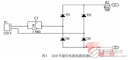
In this circuit, R1 acts as a protection resistor, while R2 limits the current to prevent voltage spikes and temperature rise. This design is ideal for small lamp cups, offering compact size, low power consumption, and cost-effectiveness. It's recommended to use a polyester capacitor with a voltage rating of 400V or higher for C1, and a 1/4W carbon film resistor for R2.
**Component Parameters**
- C1: 474μF, 400V polyester capacitor
- R1: 1MΩ five-band resistor
- D1–D4: IN4007 rectifier diodes
- R2: 510Ω, 1/4W carbon film resistor
- LEDs: 38 high-brightness white LED "straw hat" type
**Production Process**
1. Before starting, all components must be tested with a multimeter to avoid faulty parts causing circuit issues. Especially LEDs, since they are connected in series, a single defective one will prevent the circuit from working. To test LEDs, use the multimeter’s ×10k range, similar to testing a regular diode. Other ranges may not work correctly.
2. Solder the DC drive circuit board. Components like diodes and resistors are placed horizontally, while capacitors are mounted vertically.
3. Solder the LED board according to the layout shown in Figure 3.
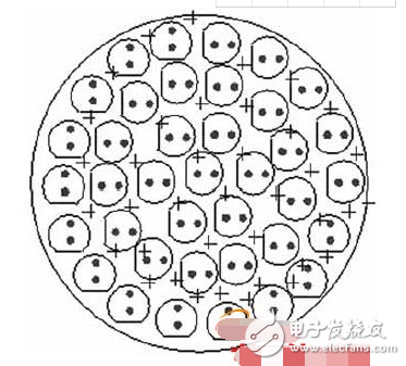
*Figure 3: LED Arrangement Rules*
The LEDs should be neatly arranged, with correct polarity. The longer pin is positive, and the shorter one is negative. A simple way to ensure correct installation is to align the LED with the notch and solder it with a suitable iron. Afterward, trim the excess pins with diagonal cutters.
4. Connect the AC power leads (marked AC) and the LED power leads (marked + and -).
5. Secure the DC drive board to the lamp cup using hot melt adhesive, insert the LED board into the slot, and fasten the back cover.
This process ensures a reliable and efficient LED energy-saving lamp that is both durable and user-friendly.