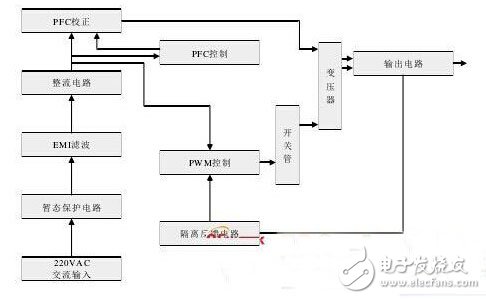
This article is based on the UC3842 high performance current mode pulse width modulation (PWM) generator controlled switching power supply, suitable for use in such medical systems. The experiment realizes the isolation of output and input through optocoupler, which not only improves the efficiency of the power supply, simplifies the peripheral circuit, but also reduces the cost and volume of the power supply, so that the power supply has the advantages of stable output voltage and small ripple. Taking the UC3842 chip as the core, a medical switching power supply design scheme is proposed. Firstly, the basic principle of UC3842 is expounded. On this basis, the principle and design method of single-ended flyback switching power supply are proposed. UC3842 is a current-type pulse width modulator introduced by Unitorde. The single-ended output of the modulator can directly drive a bipolar power tube or FET. It is suitable for the design of 20~80W low power switching power supply without power frequency transformer. The design scheme introduced by the article adopts single-ended flyback structure to realize wide voltage input, stable DC output, small input ripple, stable output, small size, light weight, high efficiency, good electromagnetic compatibility, etc. To meet the power supply needs of medical equipment. introduction In recent years, with the rapid development of power supply technology, the switching power supply has the advantages of high efficiency, low power, small size and light weight compared with the linear power supply of the same capacity. Since the 1990s, switching power supplies have been widely used in a variety of electronic and electrical equipment, communications, power detection equipment power supply. At the same time, it has been widely used in medical equipment, such as electrocardiograph, infusion pump, ultrasonic diagnostic equipment, monitor, CT machine and so on. The quality of the switching power supply directly affects the reliability of the entire medical electronic device. Therefore, the design of the switching power supply has been paid more and more attention in the design of medical equipment. The article is based on the UC3842 high-performance current mode pulse width modulation (PWM) generator controlled switching power supply suitable for use in such medical systems. The experiment realizes the isolation of output and input through optocoupler, which not only improves the efficiency of the power supply, simplifies the peripheral circuit, but also reduces the cost and volume of the power supply, so that the power supply has the advantages of stable output voltage and small ripple. 1 UC3842 chip introduction UC3842 is produced by UNIRODE, USA. This IC has the advantages of less pins (8 pins), fewer external components, simple wiring, high reliability and low cost. The UC3842 is a current controlled pulse width regulator. Usually used in single-ended flyback converters. Its internal structure is shown in Figure 1. Figure 1: Internal equivalent circuit of UC3842 In the figure, pins 1 and 2 are the inverting input terminals of the compensation terminal and the internal voltage comparator; pin 3 is the current detection input terminal, and an external overcurrent detecting resistor can constitute an overcurrent protection circuit. When the voltage of the 3 pin is equal to or higher than At 1 V, the current control detects that the comparator outputs a high level, resets the PWM latch, thereby turning off the output pulse; the 4-pin is connected to the oscillating circuit, and the sawtooth wave RT of the desired frequency is connected between the 4 and 8 pins, and the CT is connected. Between the 4 feet and the ground, 5 feet are ground; 6 feet are the output end, which has the ability of pulling and sinking current, and can directly drive the bipolar power tube or MOS tube. Pin 7 is its power supply terminal. The chip operates with a turn-on voltage of 16 V and an undervoltage lockout voltage of 10 V. The 8-pin is its internal reference voltage (5 V). 2 Switching power supply structure and working process The basic circuit of the switching power supply used in medical equipment is composed of an input circuit, a power conversion circuit, an output circuit and a control circuit, as shown in FIG. 2 . Figure 2: Block diagram of the switching power supply The input circuit includes a rectifier circuit, an EMI filter circuit, and a transient protection circuit. The rectifier circuit converts the input AC into a direct current. Generally, the rectifier circuit in the switching power supply adopts a capacitive input type. The EMI filter circuit consists of a capacitor and a coil. Its function is to filter out high-frequency clutter and in-phase interference signals in the power grid, and to avoid electromagnetic interference generated in the power supply from leaking to the outside. The transient protection circuit has lightning protection, starting impulse current limit and input overcurrent protection. The power conversion circuit is the core part of the switching power supply and is mainly composed of a switching circuit and a transformer. Switching transistors should use fast switching speed, conduction and short working time. Generally, the control mode of the power switch tube selects pulse width modulation. The output circuit rectifies the secondary square wave voltage of the high frequency transformer into a unidirectional ripple current and smoothes it into a low ripple DC voltage required by the design. At the same time, the output voltage of the direct current is used as the feedback signal, and the voltage is adjusted by the PWM control circuit of the previous stage through the isolated feedback circuit to achieve the purpose of voltage regulation. The main function of the control circuit is to provide a rectangular pulse sequence to the drive circuit to control the pulse width and frequency to achieve the purpose of changing the output voltage. 3 flyback switching power supply design The article uses UC3842 as the core device to design a single-ended flyback switching regulator power supply. The switching power supply control circuit is a voltage and current double closed loop control system. The circuit diagram of the switching regulator power supply is shown in Figure 3. Figure 3: Switching regulator power supply circuit diagram Waterproof Speaker,Full Range Loud Speaker,Entrance System Speaker,Waterproof Multimedia Speaker Jiangsu Huawha Electronices Co.,Ltd , https://www.hnbuzzer.com