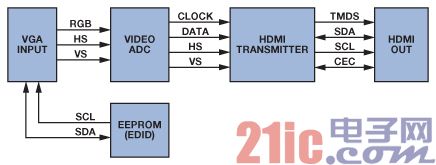
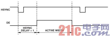
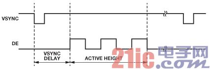
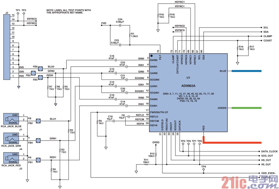
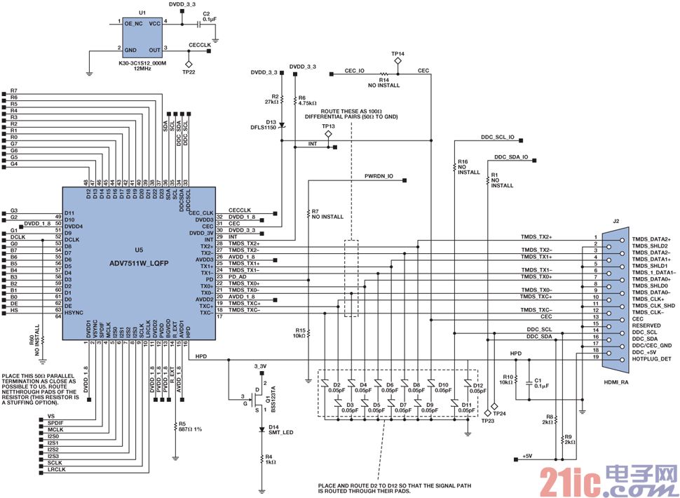
In the consumer electronics market, television, projectors and other multimedia devices have adopted High Definition Multimedia Interface (HDMI®) technology, making HDMI a globally recognized interface. I believe that all multimedia devices will need to be equipped with this interface soon. The HDMI interface has become popular in home entertainment, and it has become increasingly popular in portable devices and car infotainment systems. This article refers to the address: http:// Achieving a standardized multimedia interface is an inevitable requirement of the highly competitive consumer electronics market, and time to market is critical to the market. In addition to increasing market acceptance, standard interfaces can greatly improve compatibility between projectors, DVD players, HDTVs, and other devices from different manufacturers. However, in some industrial applications, the transition from analog video to digital video takes longer than the consumer electronics market, and many devices have not yet adopted new digital methods to send synthesized audio and video data. These devices still use analog signals as the only video transmission path, possibly because of specific requirements for specific markets or applications. For example, for projectors, some customers still prefer to use a video graphics array (VGA) cable, while others use an audio/video receiver (AVR) or media box as a hub to connect an HDMI cable to the TV instead of a A messy and unsightly cable, as shown in Figure 1. Figure 1. Media box converts analog signals to HDMI New users may consider HDMI to be a relatively complex standard that requires proven software drivers, interoperability, and compatibility testing to ensure that a device works properly when used in conjunction with a variety of other devices. This seems a bit difficult to grasp, and this often happens when new technologies are encountered. However, advanced semiconductor technologies are addressing these challenges, both analog and digital domains have been improved, including balancing higher differential signals with higher performance modules and using more sophisticated algorithms to reduce software overhead and correct bit errors. . This article explains how advanced semiconductor solutions and smart software can help achieve HDMI. Two basic devices, HDMI-VGA ("HDMI2VGA") and VGA-HDMI ("VGA2HDMI") converters, provide a simple way for engineers familiar with video applications to convert analog video to digital video. Although HDMI has become the de facto HD video interface, VGA is still the most commonly used interface on laptops. This article also explains how to interconnect these two interfaces. Introduction to HDMI Applications and Video Standards The HDMI interface utilizes the Minimum Differential Transfer Signal (TMDS) line to transmit video, audio, and data in the form of packets. In addition to these multimedia signals, the interface includes display data channel (DDC) signals for exchanging extended display identification data (EDID) and high bandwidth digital content protection information (HDCP). In addition, the HDMI interface can be equipped with consumer electronic control (CEC), audio feedback channel (ARC) and home Ethernet channel (HEC). Since these are not an important part of the application described herein, they will not be discussed in this article. The EDID data includes a 128-byte (VESA-Video Equipment Standards Association) or 256-byte (CEA-861-Consumer Electronics Association) data module to illustrate the video and (optional) audio capabilities of the video receiver (Rx). The EDID is read from the video receiver by the video source (player) over the DDC line using the I2C protocol. The video source must send the preferred or best video mode supported by the video receiver and listed in the EDID. The EDID may also contain information about the video receiver's audio capabilities, as well as a list of supported audio modes and corresponding frequencies. Both VGA and HDMI have DDC connections to support communication between the video source and the receiver. The first 128 bytes of EDID can be shared by VGA and HDMI. According to ADI's HDMI Compatibility Test (CT) lab, the first 128 bytes of EDID are more prone to errors because some engineers are not familiar with the stringent requirements of the HDMI specification, and most articles focus on the EDID expansion module. Table 1 shows the error-prone part of the first 128 bytes of EDID. For more information on the design of the CEA expansion module after the first 128 bytes of EDID, please refer to the CEA-861 specification. Table 1. Introduction to EDID address byte 00h 8 08h 10 08h 2 12h 2 12h 1 13h 1 18h 1 36h 72 36h 18 48h 18 5Ah 18 6Ch 18 7Eh 1 7Fh 1 80... The timing formats for VGA and HDMI are defined by the two standard setting groups: VESA and CEA/EIA. See VESA Timing and Cooperative Video Timing Standards for definitions of VESA timing formats; see CEA-861 for HDMI timing formats. The VESA timing format includes standards primarily for PCs and notebooks such as VGA, XGA, SXGA, and more. CEA-861 describes the standards used in TV and HD/HD displays, such as 480p, 576p, 720p and 1080p. Of these timing formats, only 640 × 480p @ 60 Hz is mandatory and is common to the VESA and CEA-861 standards. Both PC and TV must support this mode, so this example uses this mode. Table 2 compares the video standards that are generally supported. Please refer to the corresponding specifications for detailed data. Table 2. The most commonly used VESA and CEA-861 standards (p = progressive; i = interlaced) VESA (monitor monitoring timing) CEA-861 640 × 350p @ 85 MHz 720 × 576i @ 50 Hz 640 × 400p @ 85 Hz 720 × 576p @ 50/100 Hz 720 × 400p @ 85 Hz 640 × 480p @ 59.94/60 Hz 640 × 480p @ 60/72/75/85 Hz 720 × 480i @ 59.94/60 Hz 800 × 600p @ 56/60/72/75/85 Hz 720 × 480p @ 59.94/60/119.88/120 Hz 1024 × 768i @ 43 Hz 1280 × 720p @ 50/59.94/60/100/119.88/120 Hz 1024 × 768p @ 60/70/75/85 Hz 1920 × 1080i @ 50/59.94/60/100/200 Hz 1152 × 864p @ 75 Hz 1920 × 1080p @ 59.94/60 Hz 1280 × 960p @ 60/85 Hz 1440 × 480p @ 59.94/60 Hz 1280 × 1024p @ 60/75/85 Hz 1440 × 576p @ 50 Hz 1600 × 1200p @ 60/65/70/75/85 Hz 720(1440) × 240p @ 59.94/60 Hz 1920 × 1440p @ 60/75 Hz 720(1440) × 288p @ 50 Hz Introduction to applications and some requirements An important requirement for the HDMI2VGA and VGA2 HDMI converters is to ensure that the signals sent by the video source conform to the correct video standards. This is done by providing a video source with the appropriate EDID content. Once received, the correct video standard can be converted to the final HDMI or VGA standard. The functional block diagrams in Figures 2 and 3 show the corresponding process for HDMI2VGA and VGA2HDMI conversion. The HDMI2VGA converter assumes that the HDMI Rx has an embedded EDID. Figure 2. HDMI2VGA converter with audio extraction Figure 3. VGA2HDMI Converter working principle VGA2HDMI: The VGA source reads the EDID content from the receiver, uses the DDC line channel to obtain a supported timing list, and then the video source begins to send the video stream. The VGA cable has RGB signals and independent horizontal (HSYNC) and vertical (VSYNC) sync signals. The downstream VGA ADC locks HSYNC to regenerate the sample clock. The VGA decoder aligns the input sync signal with the clock. The Data Enable (DE) signal indicates the active area of ​​the video. The VGA ADC does not output this signal, which is a mandatory requirement for HDMI signal encoding. The logic high portion of DE represents the effective pixel, or the visible portion of the video signal. The logic low level portion of DE represents the blanking portion of the video signal. Figure 4. Horizontal DE generation Figure 5. Vertical DE generation The DE signal is critical to generating an effective HDMI stream. If there is no DE signal, it can be compensated by the HDMI transmitter (Tx), which can regenerate the DE signal. Modern HDMI transmitters can generate DE signals from the HSYNC and VSYNC inputs (as shown in Figures 4 and 5) using several parameter settings such as HSYNC delay, VSYNC delay, effective width and effective height to ensure compatibility with HDMI signal transmission. The HSYNC delay defines the number of pixels from the leading edge of HSYNC to the leading edge of DE. The VSYNC delay defines the number of HSYNC pulses between the VSYNC and DE leading edges. The effective width represents the number of effective horizontal pixels, and the effective height represents the number of lines of valid video. The DE generation function can also be used for display functions, such as placing the active video area in the center of the screen. Display position adjustment is a mandatory requirement for VGA input. The first and last pixels of the digitized analog input signal must not be close to or coincide with any HSYNC/VSYNC pulses. The DE signal low period (such as vertical or horizontal blanking interval) is used to send additional HDMI data and audio data packets, and must not violate the requirements. This misalignment can be caused by the ADC sampling phase. Black bars in the visible area of ​​the screen may mean that the active areas are not aligned. For composite video broadcast signals (CVBS), this phenomenon can be corrected by overscan 5% to 10%. VGA is designed to display the entire active area without dropping any area. The screen will not be scanned, so the display position adjustment is important for VGA to HDMI. In the best case, the black bars can be automatically recognized, the images can be automatically adjusted to the center of the final screen, or manually adjusted based on the readback information. If the VGA ADC is connected to the back end scaler, the active video will be properly realigned with the entire viewable area. However, using a scaler to solve the problem of misalignment of effective video regions increases design costs and associated risks. For example, with a scaler and a video pattern, the black area around a small white frame in the active area may be treated as a useless stick. Eliminating the black area around a small white frame in the active area may be considered a useless strip. It will be eliminated. When the black area is removed, the white frame becomes a pure white background. On the other hand, a half-white and a half-black image produces distortion. In order to prevent such improper distortion, some kind of prevention mechanism must be taken. Once the HDMI Tx locks and regenerates the DE signal, it sends a video stream to the HDMI receiver (such as a TV). At the same time, on-chip audio devices, such as audio codecs, can also send audio streams to the HDMI Tx via I2S, S/PDIF or DSD. One of the advantages of HDMI is the ability to send both video and audio. After the VGA2 HDMI conversion board is powered and the source and receiver are connected, the MCU should read back the EDID content of the HDMI receiver through the HDMI Tx DDC line. The MCU should copy the first 128 bytes of the EDID slightly to the EEPROM of the VGA DDC channel, as the VGA DDC channel generally does not support CEA extensions for HDMI. Table 3 lists the required changes. Table 3. List of changes required for the VGA2HDMI converter change the reason EDID 0x14[7] changes from 1 to 0 Indicates analog VGA input Change existing timing, standard timing, preferred timing, and detailed timing Timing beyond the maximum supported by the VGA converter and HDMI Tx must be changed to maximum timing or small timing 0x7E is set to 00 No EDID expansion module Change 0x7F The checksum must be recalculated based on the above changes HDMI2VGA: The HDMI2VGA converter must first provide the appropriate EDID content to the HDMI source before receiving the required 640 × 480p signal, or other common standards supported by the video source/display. HDMI Rx typically stores EDID content internally, processes hot-swap detection lines (indicating that the display is connected), and receives, decodes, and interprets the incoming video and audio streams. Because the HDMI stream combines audio, video, and data, the HDMI Rx must also support readback auxiliary information such as color space, video standards, and audio modes. Most HDMI receivers adaptively receive streams, automatically converting any color space (YCbCr 4:4:4, YCbCr 4:2:2, RGB 4:4:4) to the RGB 4:4:4 color required by the video DAC space. Automatic color space conversion (CSC) ensures that the correct color space is sent to the backend device. After the input HDMI stream is processed and decoded to the required standard, it is output to the video DAC and audio codec via the pixel bus. Video DACs typically have an RGB pixel bus and clock input, but no sync signals. The HSYNC and VSYNC signals can be output to the VGA output through the buffer and ultimately output to a monitor or other display. HDMI audio streams can carry many different standards, such as: L-PCM, DSD, DST, DTS, high bit rate audio, AC3, and other compressed bitstreams. Most HDMI receivers have no problem extracting audio standards, but further processing may be problematic. Depending on the back-end device, it may be preferable to use a simple standard instead of a complex standard so that it can be easily converted to an analog output for the speaker. The HDMI specification ensures that all devices support at least 32 kHz, 44.1 kHz, and 48 kHz LPCM. Therefore, an EDID signal must be generated that matches both the audio capabilities of the HDMI 2VGA converter that extracts the audio and the original signal of the display that matches the original capabilities of the VGA display. This can be accomplished by a simple algorithm that retrieves EDID content from the VGA display via the DDC line. The readback data should be parsed and verified to ensure that the frequency allowed by the monitor is not higher than the frequency supported by the HDMI Rx or video DAC (see Table 4). The EDID image can be extended with an additional CEA module that lists audio capabilities to reflect that the HDMI2VGA converter only supports linear PCM standard audio. The preliminary EDID data containing all modules can therefore be provided to the HDMI source. After sending a pulse to the hot-swap detection line (part of the HDMI cable), the HDMI source should re-read the EDID from the converter. A simple microcontroller or CPU can be used to control the entire circuit, read VGA EDID and program the HDMI Rx and audio DAC/codec. There is generally no need to control the video DAC because it does not have a control port such as I2C or SPI. Table 4. List of changes required for the HDMI2VGA converter change the reason 0x14[7] changed from 0 to 1 Indicates digital input Check standard timing information and change as needed (bytes 0x26 to 0x35) Timing beyond the maximum supported by the converter and HDMI Rx must be changed to maximum timing or small timing Check DTD (Detailed Timing Descriptor) (Bytes 0x36 to 0x47) Timing beyond the maximum supported by the converter and HDMI Rx must be changed to maximum timing or smaller timing (for example, changed to 640 × 480p) 0x7E is set to 1 A module must be added at the end of EDID Change 0x7F The checksum from byte 0 to 0x7E must be recalculated Add additional CEA-861 modules 0x80 to 0xFF describes the audio Add CEA-861 module to indicate the capabilities of the audio converter Content protection considerations A typical analog VGA does not provide content protection, so independent converters should not allow decryption of content protection data, otherwise the end user will be able to access raw word data. On the other hand, if the circuit is part of a larger device, it can be used as long as it does not allow the user to access the unencrypted video stream. Circuit example The sample VGA to HDMI board uses the high-performance 8-bit display interface AD9983A, which supports the highest UXGA timing and RGB/YPbPr inputs, as well as the high-performance 165 MHz HDMI transmitter ADV7513, which supports 24-bit TTL input, 3D video, and variable input formats. These devices make it quick and easy to build a VGA2HDMI converter. The ADV7513 also has a built-in DE generation module that eliminates the need for an external FPGA to generate the missing DE signal. The ADV7513 also has an embedded EDID processing module that automatically reads back EDID information from the HDMI Rx or manually forces a readback. Similarly, building an HDMI2VGA converter is not very complicated. A highly integrated video path can be built using the low-power 165 MHz HDMI receiver ADV7611 and the three-channel, 8-bit, 330 MHz video DACADV7125. The Rx includes a built-in EDID, circuitry for handling hot-swap settings, an automatic CSC that outputs RGB 4:4:4 (independent of the received color space), and a support for brightness/contrast adjustment and synchronization signal realignment. Device processing module. The low-power audio codec SSM2604 decodes the stereo I2S stream and outputs it at any volume through the DAC. The audio codec's clock source is available from the ADV7611 MCLK line. It does not require an external crystal and the configuration requires only a few writes. A simple MCU, such as the ADuC7020, a precision analog microcontroller with built-in oscillator, controls the entire system, including EDID processing, color enhancement, and a simple user interface with buttons, scroll bars, and knobs. Figure 6 and Figure 7 show example schematics of the video digitizer (AD9983A) and HDMI Tx (ADV7513), which are important components of the VGA2 HDMI converter, respectively. Does not include MCU circuits. Figure 6. Schematic of the AD9983A Figure 7. Schematic of the ADV7513 Conclusion ADI's audio, video, and microcontroller devices enable a highly integrated HDMI2VGA or VGA2HDMI converter that delivers a small amount of power from a USB connector. Both converters show that applications using HDMI technology can be easily implemented with ADI devices. For devices that should operate in an HDMI repeater configuration, the HDMI system complexity will increase as this requires handling the HDCP protocol and the entire HDMI tree. Both converters do not use an HDMI repeater configuration.
The High-mast Lamp is generally refers to the new lighting device which is composed of the steel taper light pole and the high power combination lamp frame of 15 meters or above.It consists of lamp holder, internal lamp, electric rod body and basic part.Lamp head modelling can according to user requirement, surroundings, lighting need specific and definite;The interior lamps are mainly composed of floodlights and projection lamps. The light source adopts NG400 high pressure sodium lamp, and the lighting radius is 60 meters.The bar body is usually a pyramid structure, which is made of steel plate, with a height of 15 to 40 meters, which consists of two to three sections.
Material characteristics
1. Beautiful appearance, large lighting area, good lighting effect, concentrated light, uniform illumination, small glare and easy to control and repair.
2. Applicable places: city square, station, wharf, highway, stadium, overpass, etc.
3. The lamp pole is a high quality steel plate by moulding into a multi - pyramid splicing steel rod, through hot galvanizing anti-corrosion treatment.
4. The lamp frame is made of high quality stainless steel.
5. Fasteners bolts and nuts are stainless steel.
6. Light source:400W-1000W sodium lamp.
Specifications:
Height: from 18m to 50 m
High-Mast Lamps Series,High Mast Lamps,High Mast Light,High Mast Light Pole Jiangsu chengxu Electric Group Co., Ltd , https://www.chengxulighting.com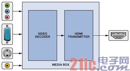
description Comment Header: (00 FF FF FF FF FF FF 00)h Must have fixed module header Supplier and product identification ID manufacturer name Three compressed ASCII characters released by Microsoft® EDID structure version and revision Version number: 01h fixed Revision No.: 03h fixed Feature support Features such as power management and color types. Bit 1 should be set to 1. 18 byte data module Preferred timing mode Represents a timing that supports the production of the best quality screen image. For most flat panel displays, the preferred timing mode is the native timing of the tablet. Detailed timing #2 or display descriptor Indicates detailed timing and can also be used as a display descriptor. The display descriptor should use two words, one for the monitor range limit and one for the monitor name. The detailed timing module should be in front of the display descriptor module. Detailed timing #3 or display descriptor Detailed timing #4 or display descriptor Number of expansion modules N The number of subsequent 128-byte EDID expansion modules. Checksum The sum of 1 byte of all 128 bytes in this EDID module should be equal to zero. Module mapping or CEA extension 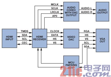


Suit for: highway, expressway, parkway, freeway, central motorway junction, truck and bus terminals, railyards, ship docks, airports, ferry terminals, prisons, industrial and commercial sites, international borders.
Shape: round, multi-pyramidal, column form, polygonal or conical
Material:
Q345B/A572,minimum yield strength>=345n/mm2
Q235B/A36,minimum yield strength>=235n/mm2
Tolerance of Dimension: ±2%
Lighting Source: 400 W- 5000 W high pressure sodium flood light, light extension :up to 30 000 m²
Light plate: Various figure of selection ,material with hot dip galvanization steel frame
Lifting System: Lifter fixed in the inner of the pole with lifting speed of 3~5 meter per minute
Equipped e; ant ferromagnetism brake and break -proof device, manual operation applied under power cut
Electric Appliance Control Device: Electric appliance box to be the hold of the pole ,lifting operation could be 5 meter away from the pole through wire .Time control and light control could be equipped to realize full-load lighting mode and part lighting mode
Surface treatment: Hot dip galvanized Following ASTM A 123, color polyester power or any other standard by client required.
Joint of Poles: Insert mode, inner flange mode, face to face joint mode .
Design of pole: Against earthquake of 8 grade
Wind Speed: 80 Km/Hour
Welding: We has past flaw testing. Internal and external double welding makes the welding in shape
Thickness: 6 mm to 20 mm
Production Process:
Raw material test→Cutting→Molding or bending →Welding (longitudinal ) →Dimension verify→Flangewelding→Hole drilling →Calibration →Deburr →Galvanization or powder coating, Painting→Recalibration→Thread→Packaging
Packages: Our poles as normal cover by Mat or straw bale at the top and bottom ,anyway also can following by client required