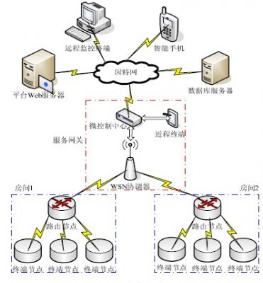
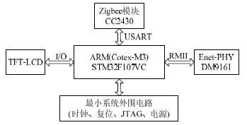
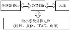
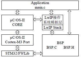
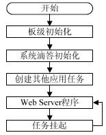
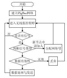
0 Preface With the rapid development of the Internet of Things technology, the trend of integrating the traditional Internet with the new wireless sensor network is becoming more and more obvious. The embedded service gateway is both the coordinator gateway of the wireless sensor network and the server of the remote WEB. Communication between networks of different protocols. It is also a key device for connecting the wireless sensor network to the Internet to realize the concept of the Internet of Things. The Internet of Things service gateway will play a very important role in the future Internet of Things era, and it will become the link between the Internet of Things perception layer network and the traditional communication network. The IoT gateway can realize protocol conversion between the sensing network and the basic network and different types of sensing networks, and can realize wide area interconnection and local area interconnection. And has a wide range of sensing network access, communication protocol conversion and powerful system management. Service gateways designed with embedded systems can effectively reduce costs and take advantage of the popularity of home intelligence. 1 system overall structural design The overall structure of the system is shown in Figure 1. The mobile smart terminal or computer at the far end accesses the wireless sensor network over the Internet, while the embedded web server provides interactive page access. If the amount of access data is large or needs to be statistically analyzed, processed, and processed, then a web server and a database server need to be established. The smart home in the IoT framework is a complex system that requires multiple people to work together, such as the design of an Internet database server and the establishment of a layer of awareness. The paper focuses on the design of the service gateway, including the integrated terminal consisting of embedded WEB, short-range terminal and WSN coordinator. It is a bridge between two heterogeneous networks and plays an important role in connection [3]. Figure 1 System overall frame 2 system hardware design The hardware of the smart home system in this design consists of three parts: the service gateway, the terminal node and the routing node. (1) Service Gateway The hardware block diagram of the service gateway is shown in Figure 2. By ARM main controller, Zigbee module, Ethernet PHY, TFT-LCD The touch screen and the minimum system module are composed of 5 parts. Figure 2 Service Gateway Hardware Box The main controller uses an STM32F107 interconnected microcontroller based on the ARM (Cotex-M3) core. It has 64K SRAM, Rich memory and peripheral resources such as 256K FLASH and Ethernet MAC. The Zigbee module is a master chip of TI's CC2430. In the service gateway, it is the coordinator of the WSN, and realizes data communication with the main controller through the USART. The Ethernet module uses the physical layer chip DM9161A of Ethernet, and is connected to the main controller through RMII. The 50M clock is provided by the MCO of ARM. The LCD touch screen is connected to the ARM via an I/O interface for human-machine dialogue. (2) Terminal node and routing node The sensor node is the most basic unit that constitutes the sensor network, and mainly consists of a radio frequency communication module and a sensor data acquisition module. terminal The nodes are the same as the hardware of the routing node, and the difference is mainly in the software. The hardware diagram of the terminal node is shown in Figure 3. According to the characteristics of CC2430, it is a Zigbee protocol stack and RF RF module. And the enhanced 51-core SOPC, which can handle data processing collected by digital or analog sensor modules and pass-through tasks in WSN. Figure 3 terminal node hardware box 3 system software design The system software is divided into service gateway software running on ARM and WSN gateway software running on CC2430 module. Taking into account the complexity of the overall design of the service gateway software and the hierarchical modular design concept, the system uses the embedded operating system uCOS-II as the management of system resources, and tasks the system functions. The overall design block diagram of the service gateway software is shown in Figure 4. Figure 4 Service Gateway Overall Design Box 3.1 Service Gateway Software Hierarchy The service gateway software hierarchy is divided into: the underlying driver layer, the system layer, and the application layer. (1) The underlying driver layer The underlying driver layer includes FWLib and BSP. FWLib is the driver support software that ST has introduced to support its ARM. Provides system initialization functions, support for interrupts and operating systems, memory allocation, and drive for all on-chip peripherals to facilitate software development. In addition, users should also develop a board support package (BSP) for the application. In this system, the content of the BSP is mainly the hardware driver related to the application development board. (2) System layer The system layer includes the operating system and middleware software LwIP. The operating system is the management of software and hardware resources, and other parts of the software are Be centered on the operating system. During the migration process of the operating system, the main task is to rewrite the relevant parts of the processor and the compiler, support the application task upwards, and connect the driver downwards to realize the operation of the hardware [4]. LwIP is a TCP/IP protocol stack for embedded systems. This program contains basic functions: TCP, IP, UDP, ICMP. LwIP's operating system emulation layer provides the convenience of porting to the operating system because it includes mechanisms for communication between tasks: semaphores, message mailboxes. (3) Application layer Based on the principle of modularity and functional independence, this design divides all applications into seven application tasks, which are leading the way. Root tasks, keystroke tasks and LCD display tasks related to input and output, TCP send tasks and TCP timeout retransmission tasks associated with embedded WEB, serial data transmission tasks and Zigbee control command tasks associated with the WSN coordinator. 3.2 Software Design Process The software design process is divided into service gateway root task software design flow and WSN gateway software design flow. (1) Service Gateway Root Task Software Design Process In the operating system environment, each task is a relatively independent functional module with infinite loops. Usually there is a root task, which should This is the core functional service of the system. Figure 5 shows the root task flow diagram. First, the board-level initialization is the abstraction and encapsulation of the hardware, providing a more friendly interface for the application. Then create the remaining 6 application tasks, creating a format similar to creating a start task. Finally, the program enters the main loop program of the WEB service. In order to enable other tasks with lower priority to execute, the task suspend function must be called. Figure 5 Root task flow (2) WSN gateway software design process The WSN gateway is also called the WSN coordinator, which is the total control center of the entire sensor network and the convergence point of data collection, wireless sensing. The nodes are distributed within their coverage [5]. The software flow diagram of the sensor network gateway is shown in Figure 6. The program begins to build a Zigbee network, at which point there are no other nodes in the network. Then enter the wireless monitoring program to find out whether there is a signal requesting to join the network. If there is a new node signal request, add the network according to the signal type and assign the network number. If it is not a new node, it is determined that the data transmitted by the node is valid. Sex, valid, then received and sent to the ARM gateway, otherwise discarded. Figure 6 WSN Gateway Software Process 4 Conclusion This paper systematically discusses the IoT Service Gateway, a key technology based on IoT applications, and combines home automation for application design. On the hardware side, according to the embedded board level hardware design process, a low cost gateway hardware based on ARM processor is designed and implemented. Software design uses top-down and layered design methods, combined with gateway hardware, using embedded operating systems uCOS-II and the protocol stack LwIP have built an application development platform, which provides a good software environment for application software development. Heat Sink is a kind of heat dissipation device which is easy to heat down electronic components in electrical appliances. Most of them are made of aluminum alloy, brass or bronze, sheet shape, multi-sheet and so on. In general, the heat sink should be coated with heat conduction silicone grease on the contact surface between the electronic element and the heat sink, so that the heat emitted by the components can be transmitted to the heat sink more effectively and then distributed into the surrounding air through the heat sink. Heat Sink Heat Sink,Cooled Heat Sink,Aluminum Heat Sinks,Water Cooling Plate Heat Sink Dongguan Formal Precision Metal Parts Co,. Ltd , https://www.formalmetal.com