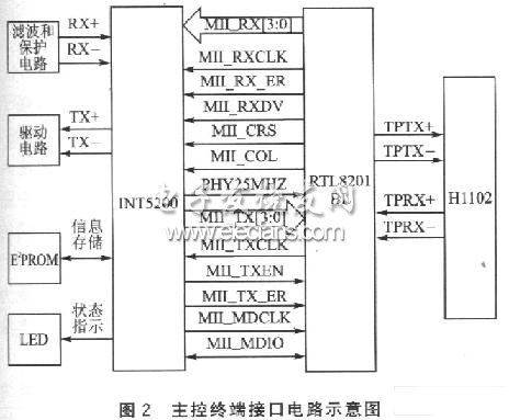
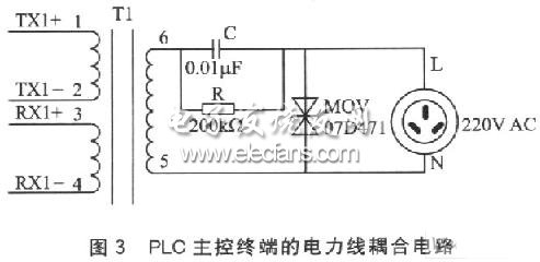
At present, China's smart home systems are mainly based on intelligent security, and are gradually extending to the networked control of home appliances. How to solve the problems of security, intelligent control of home appliances, and Internet access more effectively has gradually become a research hotspot. Power line communication (Power Line CommunicaTIon, PLC) refers to the communication technology that uses medium and low voltage power lines as the communication medium to realize the transmission of comprehensive services such as data, voice, and images. The use of PLC to achieve network control of smart homes does not require wiring, does not damage the residential structure, and is convenient and fast to connect. It is an ideal choice for smart home networked control. This system uses Intcllon's INT5200 chip as the power carrier chip. The network data is transmitted by the power line connected to the household appliances and interacts through the HomePlug protocol. OFDM (Orthogonal Frequency Division MulTIplexing) orthogonal frequency division multiplexing technology is used for modulation and demodulation In order to achieve home appliance control, PLC Internet access and home security. 1 Structure of networked control system Figure 1 is a schematic diagram of the structure of a PLC networked control system. The modem is an existing modem of ADSL or cable TV coaxial cable. After the PLC main control terminal receives the network signal demodulated by the modem, it converts it into a data packet for power line communication, and performs encryption, OFDM modulation, D / A Conversion, amplification and other processing, and then couple the power line differential signal to the phase line and neutral line of the household 220V AC power line through the coupling circuit. In this way, at any power outlet in the home, the power line differential signal can be obtained through the coupling circuit; then the power line signal is filtered, A / D converted, gain adjusted, OFDM demodulated, etc. through the PLC local office communication interface; then The data is restored to the standard network information and sent to the PC network card, or directly based on the content of the received information, through the PLC local end microprocessor to control other home appliances and security control equipment. In the same way, the data and status information of PC, other home appliances or security control equipment can also be transmitted to the PLC main control terminal according to the reverse process, and sent to the Internet through the Modem for remote users. 2 PLC main control terminal of smart home system PLC main control terminal is mainly composed of main control terminal interface and power line coupling. The main function of the PLC main control terminal is to realize the mutual conversion between Ethernet data packets and power packets, OFDM modulation and demodulation, and the coupling of signals and power lines. Among them, the main control terminal interface is composed of INT5200, Ethernet PHY chip RTL8201BL, network isolation transformer H1102, receiving filter circuit and protection circuit, sending drive circuit, E2PROM storage device, LED status indication part and power line coupling circuit. Its circuit structure is shown in Figure 2. INT5200 is a transceiver that integrates the power line MAC layer, PHY layer and analog front end (AFE). INT5200 adopts orthogonal frequency division multiplexing (OFDM) modulation and demodulation technology, selects the available carrier frequency according to the signal-to-noise ratio, solves the problems of noise source interference and multi-path attenuation, and achieves up to 14 Mbps in the harsh power line communication environment Reliable transmission. The MAC layer of TNT5200 adopts priority-based CSMA / CA mechanism and automatic answer (ARQ) mechanism, and repackages Ethernet data to achieve reliable transmission of data packets. The integrated analog front end (AFE) of INT5200 realizes the functions of signal amplification, filtering, A / D conversion and D / A conversion. In the PLC main control terminal circuit, INT5200 works in the host mode. INT5200 and RTL8201BL communicate through the MII interface, and send and receive Ethernet data packets. The MII interface provides an independent 4-bit data transceiver channel, and RTL8201BL provides a synchronous clock signal for INT5200. The MII interface has a two-wire serial data management interface (MII_MDCLK and MII_MDIO), through which you can access the registers of the RTL820lBL. When receiving power information from the power line, the main control terminal first extracts the power information from the 220V power line through the coupling circuit, and then passes the filtering, gain adjustment and other processing and sends it to INT5200. INT5200 demodulates the received power information, and then restores it to an Ethernet data packet, and sends it to the ADSL or cable TV modem via RTL8201 and H1102. In this way, the PLC main control terminal can be connected to the external Internet through the Modem. The process of sending data information to the power line is the reverse of the receiving process. Before sending data to the power line coupling, considering the attenuation during signal transmission, the driver circuit is used to amplify the transmitted information to a certain degree to enhance the signal strength. The E2PROM storage unit uses AT93C46 to store configuration information (including MAC address, network password, gain adjustment parameters, etc.), and communicates with INT5200 through the SPI interface. The LED indicator is used to display the LINK and ACT status of the network. If you want to transmit data through the 220 V home power line, you must adopt a suitable coupling method. When designing the coupling method of the power line, the particularity of the power line communication environment must be considered, and the impedance of the power line is low, generally tens of Ω. Figure 3 is the power line coupling circuit of the PLC main control terminal, where TXl + and TXl- are used to connect the drive circuit in FIG. 2 and are the power data information sending end of INT5200; RXl + and RX1- are used to connect the filter protection circuit in FIG. 2, It is the power data information receiving end of INT5200. A varistor MOV (07D471) is connected in parallel between the phase line and the neutral line to prevent surges on the power line and prevent damage to the system. Capacitor C and the secondary of the coupling transformer form a high-pass filter, which can pass the power data information and prevent the low-frequency signal of the AC power supply from passing. When the device is disconnected from the power line, the resistance R can be used to release the energy in the capacitor. RS232/485/422 serial to Ethernet server is an Ethernet TCP /IP protocol compliant bidirectional conversion transmission equipment, changing traditional serial to network communication, can directly access to the network serial devices through software. Compact designed, durable, user-friendly interface allows you to stable and reliable serial networking solutions. RS485/RS422/RS232 Serial To Ethernet Converter RS485 Serial To Ethernet Converter,RS422 Serial To Ethernet Converter,RS232 Serial To Ethernet Converter Shenzhen N-net High-Tech Co.,Ltd , http://www.nnetswitch.com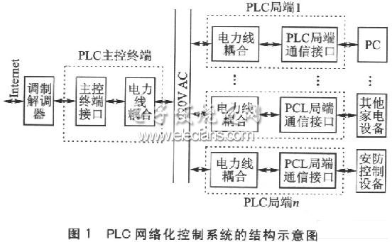
Serial port, Ethernet port and power port with surge protection
Surges, often aroused by transient high voltage generated by lightning etc., can cause damage to the electrical equipment. Surge protection takes leading technology to protect serial port, Ethernet port and power port. Equipped with serial networking solution, it stops electrical equipment away from the interference of voltage variations and electrical noise.