Design and Implementation of Automotive Communication Network Based on CAN / LIN Bus
With the continuous development of automotive electronic technology and network technology, people have higher and higher requirements for automotive safety and reliability. In order to solve the communication problems caused by the increase of automotive electronic components, this requires the use of a High-speed, multi-channel, shared car communication network. At present, a variety of buses have been developed, such as CAN (Controller Area Network) controller local area network [1], LIN (Local Interconnect Network) local area network, FlexRay, Most and so on. But CAN and LIN constitute the most extensive bus form on the car at present. This article mainly introduces the network technology that has been admired by many automobile manufacturers-CAN bus and LIN bus technology.
Introduction to CAN bus and LIN bus and their respective communication protocols
Introduction to CAN bus and LIN bus
In the late 1980s, the German Bosch company developed a serial communication protocol CAN to solve the real-time data exchange between many control units and test instruments in modern automobiles, and made it an international standard (ISO11898). So far, there are more than 20 CAN bus controller chip manufacturers in the world, more than 110 CAN bus protocol controller chips and microcontroller chips that integrate CAN bus protocol controllers.
Because of its unique design and new technology, the CAN bus has outstanding reliability, real-time performance and flexibility compared with the general communication bus. CAN uses multi-master working mode, low cost, and has a very high bus utilization rate; CAN bus has a reliable error handling and error detection mechanism, using a short frame structure, short transmission time, low probability of interference; non-destructive Bus arbitration technology, the node has an automatic exit function in the case of serious errors.
In 1998, seven companies, Audi, Motorola, BMW, DaimlerChrysler, VCT, Volvo and Volkswagen, jointly proposed a new type A bus-LIN (Local Interconnect Network). LIN is a low-cost, short-distance, low-speed network. It is designed to transmit status changes such as switch settings and sensor inputs, and respond to such changes. Therefore, it is only suitable for low-speed events that do not require high transmission time. Not suitable for high-speed events such as engine control.
The LIN network is a low-cost serial communication network used to control distributed electronic systems in automobiles. The goal of L IN is to provide auxiliary functions for existing automotive networks (eg CAN bus). Therefore, the L IN bus is an auxiliary bus network. When the bandwidth and multi-function of the CAN bus are not required, such as the communication between the smart sensor and the braking device, the use of the L IN bus can greatly save costs (1/3/3 ~ 1/2 of the cost required by the CAN bus). At present L IN has become an international standard and accepted by most vehicle manufacturers and accessory manufacturers.
The main features of LIN are as follows: low cost, based on a universal UART interface; the transmission rate can be up to 20kbps; single master controller / multi-slave device mode, without arbitration mechanism; slave nodes can achieve self-synchronization without crystal oscillator or ceramic oscillator, It saves the hardware cost of the slave device; guarantees the delay time of signal transmission; it is possible to add nodes on the network without changing the hardware and software of the L IN slave node. Usually the number of nodes on a L IN network is less than 12, and there are 64 identifiers in total.
CAN bus communication protocol --- J1939 communication protocol
The J1939 protocol is based on CAN 2.0B and is the application layer protocol of the CAN bus. The J1939 protocol divides the CAN identifier into the following parts: priority (P), data page (PGN), protocol data unit (PDU) format, PDU specific field (PS), and source address (SA). J1939 / 71 Application The layer file defines the PGN of various parameters and commands for vehicle control. Table 1 shows the J1939 message format.

LIN bus communication protocol
The LIN protocol is a single-bus (12V) serial communication protocol built on a universal SCI or UART hardware interface for connecting smart sensors and actuators distributed in the vehicle to the main controller in the vehicle.
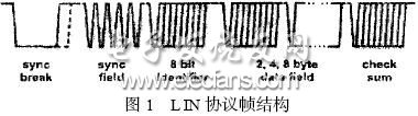
The entities transmitted through the LIN bus are frames. A message frame consists of a frame header and a response (data) part. In an activated L IN network, communication is usually initiated by the master node. The master node task sends a packet header, synchronization byte, and message identifier (ID) that contains a synchronization gap. A slave node task receives and filters The marker is activated and the transmission of the response message is started. The response contains 1 to 8 bytes of data and a one-byte check code. Figure 1 shows the LIN protocol frame structure.
#p 全 车 通信 网络 设计 # e # Vehicle communication network design
The main difference between the data transmission characteristics of ECUs in the car is the data transmission frequency. The American Society of Automotive Engineers (SAE) divides the automotive network into A (low speed: 1kbps ~ 10kbps), B (medium speed: 10kbps ~ 100kbps), C ( High speed: the highest bit rate can reach 1Mbps) 3 levels. In a perfect automotive electronic control system, many dynamic information must be synchronized with the vehicle speed, and the real-time requirements of each ECU are different due to the difference in the data update rate and control cycle. For example, the operating speed of an 8-cylinder diesel engine is 2400r / min, and the time interval between two injections controlled by the electronic control unit is 6.25ms. Among them, the crank angle of the injection duration is 30 ° (2ms), and the speed needs to be completed within the remaining 4ms A series of processes such as measurement, fuel quantity measurement, A / D conversion, actuator control, etc. This means that data transmission and reception must be completed within 1ms to meet the real-time requirements of diesel electronic control. At the same time, this requires that its data communication network is based on priority competition and has a very high communication rate. CAN bus technology is designed to meet these requirements.
However, in the Class A communication network, the parameter of the intake air temperature allows a response time of 20s, the parameter of the cooling temperature allows a response time of 1min, and the parameter of the fuel temperature allows a response time of about 10min (the above three signals are sampled every 100ms or 1min. It is completely enough), the transmission delay of front and rear light switch, seat adjustment, door opening and closing is 10 ~ 100ms. If these simpler ECU nodes are hung on the L IN bus, both the network hierarchical control and the Reduce the cost of development, production and service of vehicle electronic systems.
As shown in Figure 2, the CAN bus (1Mbps) with a high data transmission rate is used for B and C networks. The control objects are: engine controller, automatic transmission, drive anti-skid system, traction control system, ABS / ASR , Airbag controller and signal collection system of combination instrument, etc. The L IN bus is used for Class A systems with a maximum transmission rate of up to 20 kbps. The main control objects are: front and rear lights control switches, power seat switches, central door lock and anti-theft control switches, rearview mirrors, air conditioning, and window control Switch etc. These control objects do not have high requirements for the real-time nature of information transmission, but the number is large. The use of L IN bus can improve the anti-interference ability, increase the bus transmission distance, and reduce costs. Taking the door and window control as an example, there are door locks, window glass switches, window lift motors, operation buttons, etc. on the door, which can be achieved with only one L IN network. 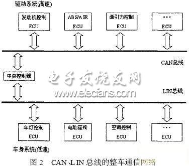
The CAN bus and the L IN bus are independent of each other, and share resources and exchange data through a central controller. The central controller is the core of the vehicle management system. It is also the gateway server of the CAN bus and the L IN bus. Its main function is to analyze and process all kinds of information and issue instructions to coordinate the work of the vehicle's control units and electrical equipment. .
Interface design
The vehicle communication network is a local area network composed of many CAN nodes and L IN nodes connected by CAN bus and L IN bus, so the interface design is very important.
Figure 3 shows the design of the interface between the central controller and the CAN bus and L IN bus. The central controller includes a CAN controller and an SCI interface. CAN intelligent node is generally composed of MCU, CAN controller and CAN transceiver.

At present, there are many manufacturers engaged in the development and manufacture of CAN bus and L IN bus chips, such as PHIL IPS, FREESCAL E, ONSEMI, TI, etc., designers can choose different chip combinations according to their needs. Here the central controller chose the MC68HC908AZ60 chip of FREESCAL E. The chip is a powerful 8-bit single-chip microcomputer designed for automotive electronics applications. It integrates a low-speed CAN controller, supports CAN2.0A / 2.0B, and has an SCI module. In addition to completing the communication connection between the L IN network and the CAN network, the chip also has other control functions.
The L IN node selects the device of FREESC2AL E. Among them, the L IN node transceiver uses MC33399; the L IN node MCU selects MC68HC805 PV8. Due to the large electromagnetic interference on the car, in order to improve the anti-interference ability of the system, the CAN controller and CAN transceiver and the L IN controller and L IN The optical isolation circuit composed of 6N137 is added between the transceivers.
The CAN intelligent node selects PHIL IPS device: PCA82C250 as CAN transceiver; the MCU of the CAN node selects P89C591, because the P89C591 integrates a CAN controller (with PeliCAN interface), so no CAN controller is selected, and its connection diagram is shown in Figure 4. Show. Designers can also choose the connection method of microcontroller + external CAN controller.
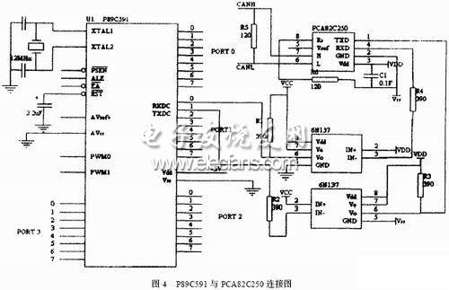
PCA82C250 provides differential transmission capability to the bus and differential reception capability to the CAN controller. At low speeds and short bus lengths, slope control is generally used to limit the rising and falling slopes and reduce RF interference. The slope can be controlled by adjusting the resistance connected from pin 8 to ground. When the communication signal is transmitted to the end of the wire, reflection will occur, and the reflected signal will interfere with the transmission of the normal signal. Therefore, termination resistors must be connected at both ends of the bus to eliminate the reflected signal. Its resistance is approximately equal to the characteristic impedance of the transmission cable.
to sum up
Class A body control based on CAN bus has been widely used in automobiles. With the increase of bus nodes on the vehicle and the development of high-performance systems to medium and low-end cars, the relatively high implementation cost of the CAN bus has become an obstacle. Compared with CAN, the communication cost of L IN node is 1/3 ~ 1/2 of CAN, which has obvious cost advantages. The automotive communication network in the article applies L IN to the body system, which not only realizes the proper network control function, but also reduces the cost of development, production and service, and has high practicality.
High efficient charging speed for Acer laptop, stable current outlet can offer power for the laptop at the same time charge the laptop battery. The best choice for your replacement adapter. The DC connector is 5.5*1.7mm or 3.3*1.0mm. We can meet your specific requirement of the products, like label design. The plug type is US/UK/AU/EU. The material of this product is PC+ABS. All condition of our product is 100% brand new.
Our products built with input/output overvoltage protection, input/output overcurrent protection, over temperature protection, over power protection and short circuit protection. You can send more details of this product, so that we can offer best service to you!
Laptop Adapter For Acer,Charger For Acer,Acer Laptop Adapter ,Ac Adapter For Acer
Shenzhen Waweis Technology Co., Ltd. , https://www.waweis.com