Global automotive semiconductors face great market opportunities, but design engineers also face technical challenges in terms of cost, power consumption, and safety. This article takes the latest intelligent transponder that can receive and send data as an example to introduce the technical methods to solve these challenges in the design of automotive wireless access systems to Chinese automotive design engineers. In China, semiconductors used in security and privacy electronic control modules account for approximately 18% of China's automotive semiconductors (. From remote keyless door control applications already in use, to passive keyless door control (PKE) systems, tires Emerging applications such as air pressure monitoring systems, electronic payment (toll collection) and Bluetooth hands-free systems, wireless systems are constantly emerging in vehicle applications. These wireless connections are a technical means to improve the performance of security and confidentiality modules, and are establishing what drivers want The characteristics of other. The emergence of other dedicated short-range wireless communication solutions for security and confidentiality applications is only limited by the availability of cost-effective technology. In addition to the traditional pressure to shorten time to market and increase functionality, design engineers also face Various challenges such as cost-effective performance enhancement, power consumption, small size and encryption security. For example, we can take a look at a wireless system that represents the many challenges facing today ’s system architects—the latest smart transponder that can receive and send data. In this two-way communication system, the base station and the transponder can communicate automatically without human intervention. This low-cost, two-way communication transponder can be designed to operate at two frequencies: 125 kHz for receiving data; UHF (315, 433, 868, or 915 MHz) for transmitting data. Due to the non-propagating nature of the 125 kHz signal, the two-way communication distance generally does not exceed 3 meters. And because the transponder also has buttons that can perform optional operations, when the transmit button is pressed, it can also support a longer one-way transmission distance (from the transponder to the base station). In these applications, the base station sends commands at a frequency of 125 kHz, while waiting for a valid transponder in the vicinity to send a response back at the UHF frequency. Smart transponders are generally in receive mode and wait for any valid 125kHz base station commands. If any valid base station command is received, the transponder sends a response at UHF frequency. This is what we call "passive and keyless door control system". Because the PKE system uses a 125kHz circuit for two-way communication, a low-cost, small-size, and low-power PKE transponder can be produced using an integrated system-on-chip (SoC) intelligent microcontroller unit (MCU) with a digital and low-frequency front end. PKE system challenge As design engineers gain more system experience, they increasingly face the following challenges: how to reliably design the PKE transponder function to make it a cost-effective alternative to traditional PKE transponders, while ensuring that it can reach a specific system aims. Table 1 lists some of the main concerns and solutions faced by system design engineers. Although the PKE transponder seems to require complex and expensive circuits to achieve, the challenges faced by design engineers have been through the use of some relatively simple, around an intelligent PIC microcontroller (PIC16F639), and includes all the necessary functions to meet Low-cost circuits required for secure two-way communication are solved. Figure 1 shows an intelligent PKE system. It also has buttons for optional operations, but the main operations can be completed without any human intervention. The two-way communication sequence of PKE application is as follows: the base station uses 125 KHz frequency to send commands; the transponder uses three orthogonal LC resonant antennas to receive 125 KHz base station commands; if the command is valid, the transponder sends a response (encrypted data) through a UHF transmitter; If the data is correct, the base station receives the response and activates the switch. A challenge faced by design engineers is the cost-effective implementation of enhanced system performance. These enhancements include: communication distance, antenna directivity, small package size, encryption security, and low power consumption under door lock "on / off" conditions. A transponder design that can reliably receive base station commands within a 125 kHz signal range and maintain long battery operating time can meet key system enhancement requirements. Input sensitivity requirements for two-way communication distance In battery-powered transponder applications, the maximum communication distance with UHF (315/433/915 MHz) is about 100 meters, but with low frequency (LF, 125 kHz) the communication distance can only reach a few meters. Therefore, the communication distance of the dual-band PKE transponder is mainly limited by the command range of the 125 kHz base station. Due to the non-propagating nature of low-frequency signals, 125 kHz signals will rapidly decay with increasing distance. For example, assuming that the base station outputs an antenna output voltage of about 300 Vpp, the voltage induced by the coil antenna of the transponder at a distance of about 3 meters is only about 3 mVpp, which is equivalent to the noise level of the application environment. Therefore, how to effectively detect weak signals is a major problem faced by system design engineers. In order to increase the range of 125 kHz base station commands, the following two possible solutions can be considered: (a) increase the transmit power of the base station transmitter; (b) increase the input sensitivity of the transponder. The maximum transmission power of the base station transmitter is generally limited by government regulations. Therefore, assuming that the maximum power of the base station transmission is within the allowable range, the above second method to improve the detection sensitivity of the input signal is the only effective solution. In order to achieve a bidirectional communication distance of 3 meters, the input sensitivity of the transponder must reach about 3 mVpp. The solution of the antenna directivity problem Any radio signal radiated by the antenna unit will propagate within a certain direction angle, and the direction of signal propagation is higher (or the radiation angle is narrower) when a better-performance antenna is used. Although the low frequency (125 kHz) signal radiated by the LC resonance circuit is not as directional as the high frequency signal, it still has a certain direction. Under the given transponder design conditions, the communication distance (or induced voltage) of low-frequency signals depends on the coupling degree of the base station antenna and the transponder antenna. When the two antennas face to face, their coupling is optimal. For hands-free PKE applications, the direction in which the transponder is placed in your pocket can be arbitrary. Therefore, the chance of the transponder antenna facing the direction of the fixed base station antenna is only about 30% (x, y, z directions). But if the transponder has three orthogonal antennas, the chance can be increased to nearly 100%. The antennas are placed in the x, y, and z directions, respectively. By using three orthogonally placed antennas, the transponder can obtain the base station signal in any given direction. The wake-up filter is used to prevent the digital part from being woken up by noise or undesired input signals. Therefore, it can effectively save working current and battery energy. Power management In addition to using special filters to save battery energy, the PIC16F639 also has patented nanoWatt technology, which can provide system design engineers with greater control of on-chip peripherals, including several software-selectable speed options. An 8 MHz internal oscillator that reduces the frequency to 32 KHz. Very low sleep current consumption and fast-start internal oscillator can support low-power system design. Periodic wake-up mechanisms include low-power real-time clock operation, ultra-low-power wake-up features, and extended low-power watchdog timer. With these extensive power management features, design engineers can implement power saving concepts in application software and obtain tighter control of overall system power consumption at a lower system cost. Encryption support The patented KEELOQ encryption technology, a global standard, provides a cost-effective solution for authentication, keyless door control, and other remote access control systems, as shown in Figure 2. KEELOQ encryption technology uses industry-proven code hopping encoding (code hopping encoding) method, when the encoding device is activated, the code will automatically change and send securely. In the implementation based on the codec / decoder pair, the encoder is located at the far end and sends a rolling code ID # and the counter value; the decoder is located at the receiver and decodes the message sent by the far-end encoder. It stores the ID and counter value of the remote device it has heard, and the decoder only allows access when it hears the remote device. KEELOQ encryption is a highly secure algorithm implemented by complex formulas and a 32-bit random number generator. Conclusion of this article In the future, design engineers of wireless security access systems in automobiles may encounter various challenges. Microcontrollers such as the PIC series can provide a mature and reliable building block for wireless systems in vehicles. The implementation of a low-cost two-way communication transponder using an integrated system-on-chip solution is a good example of a wireless system that can provide drivers with enhanced safety and confidentiality. Without any human intervention, the PKE transponder can receive low-frequency base station commands and respond with encrypted data through UHF transmitters. A small PKE transponder that can be installed in the driver's pocket can automatically open and close the door without any intervention. For the parking lot entrance application, the driver can directly enter the parking lot without parking, because the system will automatically recognize the PKE transponder within the effective use distance of about 3 meters. The wireless security access system can meet the requirements of some motorists for the continuous improvement of safety and confidentiality. In addition to consumers, government authorities and car manufacturers themselves are also launching (or planning to launch) corresponding plans to improve safety and confidentiality innovation in automobiles. The next step in the security and confidentiality plan will be the integration of a single subsystem to enhance the competitive advantage of automakers by enhancing wireless security access systems.
Cable Management refers to an important step during the installation of building services (i.e. electrical services) and the subsequent installation of equipment providing means to tidily secure electrical, data, and other cables.
Our factory has already kept over 20 types Cable Management Frame in our catalogue for your selection. Mainly Cable Ring Manager for 19" size also offer 10" with 3 rings. You can choose Horizontal Wire Management Panel or vertical wire management panel in 1U and 2U.For different function, you can refer to with cover or not even with brush or not.
Cable management frame also called cable organizer or Cable Organizer, it is easy to install or uninstall. You can change the quantity and location as you like. It makes your network cables orderly, easy and effective.
19 Inch Cable Management Frame Network Cable Management, Computer Cable Management, Rack Cable Management NINGBO YULIANG TELECOM MUNICATIONS EQUIPMENT CO.,LTD. , https://www.yltelecom.com
Table 1: Main technical difficulties and solutions of PKE intelligent transponders. 
Figure 1: Intelligent passive keyless gate control (PKE) system using two-way communication 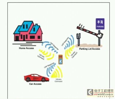
Figure 2: Various applications with wireless secure access.
Wake-up filter saves battery energy
The wake-up filter can effectively control the operation of the microcontroller PIC16F639 to save battery energy. In addition, the microcontroller must operate with minimal circuitry during the inactive mode. The PIC16F639 chip in the transponder contains a low-frequency front end and digital circuits.The low-frequency front end is always searching for input signals, while the digital part is in sleep mode to save battery consumption, and it is only awakened (or activated when a valid base station command is received. ). This can be achieved by using a special wake-up filter in the low-frequency front-end section. In addition, the low-frequency detection circuit can also be programmed to output only when the input signal has a predetermined packet header. 