Application of medium-speed infrared technology based on software coding in FTU Overview Single Burner with Built in Hob Single Burner Gas Stove,Stainless Steel Surface Hob,Single Burner Gas Cooktop,Single Burner Gas Hob xunda science&technology group co.ltd , https://www.gasstove.be
The feeder automation terminal (FTU) is the interface between the automation system and the primary equipment. It is mainly used in distribution systems such as transformers, circuit breakers, reclosers, sectioners, and load switches on columns. It is mainly installed on outdoor columns or loops. Network cabinet. Because the installation distance between the equipment and the power primary equipment is relatively close, especially the on-column installation mode brings difficulties to application update, equipment debugging, operation parameter setting and maintenance. The traditional way of debugging and maintenance through the serial port requires direct contact, often also The equipment needs to be powered off, there are hidden dangers, and the wiring is very inconvenient. The non-contact maintenance and debugging interface will solve the above problems. Compared with some short-range wireless communication such as Bluetooth, infrared data communication has low cost, simple design and good confidentiality. Infrared communication is a short-distance wireless communication technology. It uses a point-to-point transmission method, with a transmission distance of 0 to 30 m, an emission angle within 30 ° cone angle, and a maximum transmission rate of 16 Mb / s. The medium speed infrared data communication product has the characteristics of low cost, convenient connection, simple and easy to use, compact structure, long transmission distance and fast transmission rate. It is very suitable as an FTU debugging interface and solves the FTU parameter setting and maintenance. difficult.
1 Commonly used infrared data transmission specifications
1.1 IrDA protocol infrared data transmission
IrDA 1.0 protocol is based on asynchronous transceiver UART, the highest communication rate is 115.2 Kb / s. The IrDA 1.1 protocol increases the communication rate to 4 Mb / s. After that, IrDA introduced the protocol with the highest communication rate at 16 Mb / s. High-speed transmission infrared transceiver using IrDA protocol, the transmission distance is relatively short, only a few tens of centimeters, and the angle is very narrow, and the FTU is generally installed on the column, and the distance from the ground is 5 to 6 m. This method makes the field aligned with the optical axis Very difficult, the transmission distance is far from meeting the requirements. And the infrared band in sunlight will have a great impact on the sensitivity of the infrared transceiver, and bring a lot of interference.
1.2 Data transmission for infrared remote control
The transmission distance of the transceiver used for remote control is several meters to several tens of meters, and the transmission angle is usually 0 to 30 °. The transmission intensity and the receiving sensitivity are different due to the different application designs of different devices, and are widely used in small mobile devices. The standard infrared remote control wavelength is 900 ~ 950 nm, and the subcarrier is 33 ~ 40 kHz. However, the data transmission rate of the infrared transceiver used for remote control is very low. Usually only a small amount of data such as simple commands or device status are transmitted. For FTU, its debugging interface may need to observe the internal data of the device or update the program, the data that needs to be transmitted Large amount, if the rate is very low, it will cause unacceptable performance.
2 System design
FTU is installed on the outdoor column, with long distance, data rate requirements, and high interference. Therefore, Vishay medium-speed infrared transceiver is used, and CPLD / FPGA is used to realize infrared modulation and data waveform recognition, and application layer encoding and decoding are realized through software. Reduce the difficulty of hardware design and improve the anti-interference ability of the circuit.
The entire system is divided into a host-side infrared adapter and a FTU-side transceiver. The host-side adapter is connected to the computer through RS 232 and supplies power to the adapter via the USB interface. The FTU maintenance software sends and receives data through the adapter. The FTU receives the data from the host through the infrared transceiver. Commands and data, and send datagrams needed by the host to the host. The FTU is based on A1tera Nios II's SoPC system, and the signal of the infrared transceiver is connected to the processor Nios through the UART.
2.1 FTU side infrared adapter
The transceiver circuit on the FTU side includes a receiver and two infrared transmitting tubes. The signals ITXD and IRXD of the infrared transceiver can be directly connected to the two I / O pins of the FPGA. The block diagram is shown in Figure 1. 
The components in the dotted frame in Figure 1 are implemented by FPGA. A UART controller is connected to the bus of the Nios processor. The UART output TXD signal passes through the infrared modulator and the driving circuit connected to the infrared transmitting tube. The signal from the infrared receiving tube After being shaped, it is sent to the pulse width detector for decoding. The decode output of the pulse width detector is connected to the RXD of the UART. At the same time, the reset detection component detects that the reset signal is connected to the Nios control bus to control the system to restart.
2.2 Host side circuit
The infrared adapter circuit of the host side is shown in Figure 2, in which the infrared transceiver signal is connected to the serial interface of the host through CPLD and MAX232. Power supply through the serial port can simplify external wiring, but due to the long transmission distance and high transmission rate of this design, the power consumption requirements are high, and the serial port cannot provide a stable output. Therefore, the adapter is connected to the 5 V working power supply from the USB interface of the host, and the crystal oscillator Z103 is provided to the CPLD for infrared physical layer coding clock and reception signal identification. 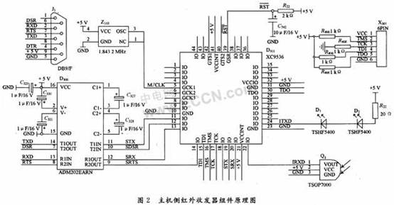
In Figure 2, R22 and C742 constitute a power-on reset, D306 and J1 constitute a host-side RS 232 interface, and the infrared emission tube is composed of D1 and D2 connected in series to enhance the transmission power and sensitivity. Q1 is infrared receiver tube, D301 is CPLDXC9536. The host side completes the infrared carrier wave generation and modulation by the CPLD and the pulse width detection and reset command generation of the received signal.
2.3 Transceiver components
The infrared emitting tube adopts Vishay's TSHF5400. TSHF5400 is a high-speed gallium arsenide infrared emitting tube with a modulation bandwidth of up to 10 MHz. At current If = 100 mA, tr = 30 ns, tf = 30 ns, optical angle φ = ± 22 °, the peak wavelength is 870 nm, and the working environment temperature is -40 ~ + 100 ℃, which is very suitable for outdoor operation.
Infrared receiver uses Vishay's high-speed receiver TSOP7000. As shown in Figure 3, it can work at 455 kHz. When paired with 870 nm infrared transmitter TSHF5400, the transmission distance can reach 20 m at If = 300 mA. 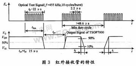
3 Physical layer modulation and width identification
Literature [8] gives several commonly used application layer transmission specifications, but it cannot meet the field safety and reliability requirements of medium-speed transmission under strong interference, so it is necessary to encode the transmitted signal and transmit it when there is no data transmission. Turn off the transceiver. The transmission adopts Manchester encoding, so there is no even 0 code and even 1 code except for the start code and the end code in the code stream. The width detection unit of the receiving part detects the code stream of the encoding field, and all three consecutive zero codes and consecutive one codes are judged as error codes.
3.1 Infrared modulation output
The physical layer transmission signal modulation and reception signal detection of the infrared transceiver are implemented by VHDL. The main clock is divided to obtain a 455 kHz data carrier. The transmission signal TXD controls the presence or absence of the data carrier to transmit data. If the current transmission signal TXD is 0, a series of data carriers are output, otherwise the output is turned off. In order to reduce the power consumption of the infrared emission tube, the duty cycle of the control data carrier is 30%.
3.2 Infrared receiving control
Infrared transmission is a half-duplex ASK modulation method. When the transmitting tube sends a logic 0, the receiving loop is closed to avoid the influence of the transmitting tube on the receiving circuit. The environment in which the FTU is installed determines its strong interference, and the probability of short burst frames being hit by interference is relatively low. This paper adds two control characters and a signal to the receiver. The detection component allows reception only when 9-bit0 is detected, and closes the reception component when 8-bit0 is received. These two characters correspond to 0x0 and 0x80, respectively, and the data is encoded and decoded by the application layer.
3.3 Infrared reset signal transmission and reception
The FTU needs to restart the system when updating the application program and changing specific operating parameters. Through the reset pulse detection component in the infrared receiving interface on the FTU side and the reset pulse generating component in the infrared transmitting interface on the host side, the host can complete the FTU Reset control.
When the host needs to reset the FTU, it only needs to generate a logic 1 to logic 0 transition on the RTS line of the RS 232 interface through the host-side interface software. The CPLD detects the transition and generates a continuous modulation output of 50 ms. Since there is no continuous low level of 50 ms in normal code transmission, the interference signal will not produce continuous level, so the reset detection component of the receiver can generate it after detecting that the infrared receiving tube continuously outputs a low level of 50 ms. The system reset signal completes the FTU restart. The entire reset logic does not depend on the application software and can be used to restart the system in an emergency.
4 Software encoding and decoding
4.1 Frame format
In this paper, the frame structure of the physical layer of the short burst frame is shown in Table 1. The start symbol 0x0 and the end symbol 0x80 are not encoded. The code word's connection 0 feature is used to start the infrared receiver and close the infrared receiver, respectively. The start character and end character are added by the driver of the sender, and the pulse width detection unit of the receiver is automatically removed. The encoding field is used to transmit user data. A user data message can be divided into multiple physical layer burst frames. The driver of the sender splits the user data according to the characteristics of the link. The receiver is responsible for reassembly. 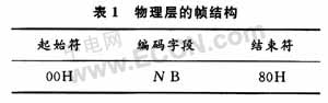
The format of the user data message used in this article is shown in Table 2. It uses character synchronization and contains a four-byte frame header of AA55EB90H, a target address of 1 B, and a frame length of 2 B (byte length of the entire encoding field) , NB data and 2 B CRC check, this part of the data requires the driver to perform software differential encoding and decoding. The actual data sent after encoding is twice the frame length.
4.2 Infrared data encoding and sending
By encoding the application layer data according to the Manchester encoding rules, it is ensured that the application data does not appear to have even 0s and even 1s. Use the following algorithm to generate the code lookup table:
(1) The loop variable is set to 0, and the encoding result value is set to 0;
(2) Take the data bit 7, if it is 1, it will be encoded as 10; otherwise, it will be encoded as 01;
(3) The data is shifted to the left by 1 bit, the encoding result value is shifted to the left by 2 bits, and the loop variable is increased by 1;
(4) If the loop variable is 7, then exit; otherwise, go to step (2) to continue coding.
In this table, 0 is encoded as 0x5555, 0xff is encoded as 0xaaaa, and so on. Since the data to be encoded is always between 0 and 255, the application layer encoding can be realized through the following lookup table. 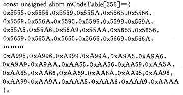
When sending, use the character to be sent as the array index, and search for the above array in turn to get the encoded output.
4.3 Infrared data decoding and receiving
Referring to the encoding algorithm, the sender 1 b is encoded as 2 b, and on the receiver, every 2 b is interpreted as a bit. Since the 8 b character received by the receiver is also located in 0 ~ 255, corresponding to the decoded 4 b, 16 b form an 8 b character. Generate the decode array as follows:
(1) The loop variable is set to 0, and the decoding result value is set to 0;
(2) Take the data bits D7 and D6, if it is 10, add 1 to the decoding result value; if it is 01, put the decoding result to 0xfe, otherwise consider it as an error and add 80 to the decoding result value to exit;
(3) The data is shifted to the left by 2 bits, the decoding result value is shifted to the left by 1 bit, and the loop variable is increased by 1;
(4) If the loop variable is 3, exit, otherwise go to step (2) to continue coding.
The hexadecimal decoding comparison table is shown in Table 3. If input 55, the decoding value is 0, and input 99 the decoding value is a, corresponding to other input decoding output is 0x80, which is an error code. 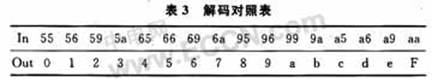
4.4 Frame reception and frame synchronization
Since an application frame is divided into multiple physical layer frames and sent using differential encoding, a character is divided into two characters, so frame synchronization is very important when decoding, otherwise the original data cannot be restored. This article takes the synchronization header as a whole, according to the encoding algorithm, the sequence 0xAA55EB90 is encoded into the sequence 0x99998666a99a9655, and the receiving program receives the sequence 0x99996666a99a9655 and immediately synchronizes the frame reception counter. According to the format of the application layer data message described in Table 2, the reception counter corresponding to the frame synchronization point is 8.
After receiving the frame synchronization sequence, it can process the data reception and synthesize an application layer character from two half characters. When the reception counter is even, the lower 4 bits of a character can be obtained according to the decode output; when the reception counter is odd, the higher 4 bits of a character can be obtained.
If the target address field is obtained when the receiving counter is 8 and 9, the low byte of the frame length is obtained when the receiving counter is 10 and 11, and the high byte of the frame length is obtained when the receiving counter is 12 and 13, and so on. Data, the entire frame synchronization and decoding process is shown in Figure 4.
4.5 Error control
In this paper, three methods of width detection, code violation detection and frame check are used to check the received frame. Frame check adopts 16-bit CRC check, and its generating polynomial is G (x) = x16 + x15 + x2 + 1. Frames with error check are discarded and retransmitted over time by the host side. Through this mechanism to identify erroneous packets, the reliability of the logical link can still be guaranteed in the case of strong interference.
Before sending the message, the sender calculates the CRC check code of the message and appends it to the frame check field of the message, and then starts the encoding program to encode and send the current datagram. The receiver program submits the received data packet to the application layer reception processing program after excluding the coding error and CRC error, as shown in Figure 4. 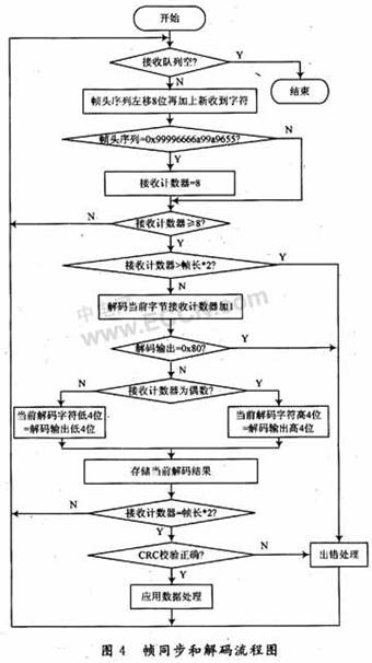
5 System software design
The logic of the entire system uses VHDL description language, CPLD design uses Xilinx ISE for logic synthesis and debugging, FTU side uses Altera SoPC Buitder to build Nios system, and complete logic design and simulation debugging in Quartus II environment. The FTU application software uses C language to complete the coding and debugging in the Nios IDE environment, and the software on the host side uses Visual Basic 6.0 to complete the console software coding and debugging. Through the cooperation of these development tools, the entire project is coded and debugged.
6 Conclusion
Because FTU is mostly installed on outdoor columns and ring network cabinets, the transmission distance is long, the transceiver alignment is difficult, and the background light is very strong. The interference of visible light and sunlight must be considered. For this application, the issues of sensitivity and anti-interference should be considered from the following aspects:
(1) A wide-angle infrared receiving tube is used, and multiple transmitting tubes are connected in series, and the drive current is appropriately increased to balance the sensitivity and power consumption, and the transceiver alignment is difficult;
(2) Use short burst frames to reduce the chance of data frames being hit by interference;
(3) Turn off the receiver when sending data locally, the application program does not process the received data when sending, and consider the timing of sending and receiving conversion;
(4) Using the method of sending end coding and receiving segment width detection described in this article, only open the receiving part when the start character is received, and close the receiving when the end character is received, reducing the receiving window;
(5) The data segment adopts error control mechanisms such as the combination of differential encoding and frame check and error retransmission, and cooperates with the software to effectively filter out error messages, which further enhances the anti-interference performance of the link;
(6) For outdoor applications, the design must also consider the effects of background light, electromagnetic interference, humidity, and temperature on the transceiver.
The mid-speed infrared transceiver circuit and software designed as described above have been successfully applied in the FTU of our company's DMP2000 distribution automation system and the intelligent collection terminal of the DMP5000 digital substation. It has been running on site for three years and is stable and reliable. Under direct sunlight at noon, the transmission distance can reach more than 5 m, and can reach 20 m at night. The data symbol rate is 38 400 b / s. The actual data transmission rate is 19 200 b / s considering the differential coding factor. The link detects errors And anti-interference ability is very strong, which greatly facilitates FTU on-site maintenance and parameter setting.