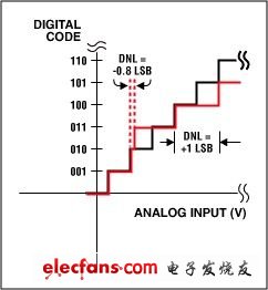
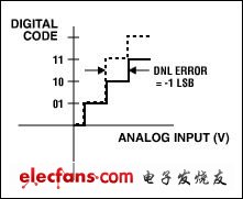
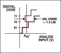
Abstract: Many engineers encounter some subtle problems in their design: ADC specifications are often lower than the system requirements. This article describes how to properly select an ADC based on system requirements and lists the various sources of error that can be encountered in ADC measurements. Using a 12-bit resolution analog-to-digital converter (ADC) does not necessarily mean that your system will have 12-bit accuracy. Many times, engineers are surprised and puzzled that the performance of data acquisition systems is often much lower than expected. If the problem was not discovered until the prototype was running, it would have to switch to a higher performance ADC in a panic, a lot of time was spent redesigning the design, and the schedule for trial production was approaching quickly. where is the problem? What factors have changed in the initial analysis? An in-depth understanding of the ADC's performance metrics will help identify some of the details that often lead to unsatisfactory performance metrics. An understanding of the ADC specifications will also help you choose the right ADC for your design. We start with the performance requirements of the entire system. Each component in the system has corresponding errors. Our goal is to limit the overall error to a certain range. The ADC is a key component of the signal path and care must be taken to select the appropriate device. Before we begin to evaluate the overall performance, assume that the ADC's conversion efficiency, interface, power supply, power consumption, input range, and number of channels meet the system requirements. The accuracy of the ADC is related to several key specifications, including integral nonlinearity (INL), offset and gain error, voltage reference accuracy, temperature effects, and AC characteristics. It is best to evaluate the performance of the ADC from the DC characteristics. Because there are many non-standard methods for the AC parameter test of the ADC, it is easier to compare the two ICs based on the DC characteristics. DC characteristics are generally more reflective of device problems than AC characteristics. System Requirements There are two common methods for determining the overall system error: root mean square (RSS), and testing under worst-case operating conditions. When using RSS, average each error, then sum and calculate the square root. The RSS error is calculated by: Where EN represents the error term for a particular circuit component or parameter. This method is most accurate when all errors are irrelevant (this may or may not be the case). Using the worst case analysis method, all error terms are added. This method ensures that the error does not exceed the specified range, it gives the error limit under worst-case conditions, and the actual error is always less than this value (usually several times lower). In most cases, the measurement error is between the two method test values, closer to the value provided by the RSS method. Typical errors and worst-case operating conditions can be selected based on the error budget. The specific choice depends on many factors, including: the standard deviation of the measured values, the importance of the specific parameters, the degree of interaction between the errors, and so on. This shows that it is difficult to find simple rules that must be followed. In our analysis, we chose the worst condition test method. In this case, let's assume that we need 0.1% or 10 bits of precision (1/210), so it makes sense to choose a converter with a higher resolution. If it's a 12-bit converter, we might assume that the accuracy is high enough; but we didn't have the 12-bit performance (the actual situation might be better or worse) before we carefully examined its specifications. For example, a 12-bit ADC with 4LSB integral nonlinearity error can only provide up to 10 bits of accuracy (assuming offset and gain errors have been corrected). A device with 0.5LSB INL provides 0.0122% error or 13-bit accuracy (after gain and offset errors are eliminated). To calculate the best accuracy, divide the maximum INL error by 2N, where N is the number of converter bits. In our example, if a 0.075% error (or 11 bit) ADC is used, the margin of error left for the remaining circuits is only 0.025%, including the sensor, front-end signal conditioning circuit (op amp, multiplexer) Etc.), perhaps digital to analog converters (DACs), PWM signals, or other analog circuits on the signal path. We assume that the total error budget of the overall system is based on the sum of the error terms of the various circuit components of the signal path. We also assume that a slowly varying DC, bipolar input signal will be measured with a bandwidth of 1 kHz and an operating temperature range of zero. °C to 70 ° C, and performance in the range of 0 ° C to 50 ° C. DC performance Differential nonlinearity Although not considered as a key ADC parameter, differential nonlinearity (DNL) error is the first indicator into our field of vision. DNL reveals the spacing between an output code and its neighboring code. This interval is obtained by measuring the amplitude change of the input voltage and then converting it to LSB (Figure 1). It is worth noting that INL is the integral of DNL, ​​which is why DNL is not considered a key parameter by us. A well-performing ADC often claims "no missing codes." This means that when the input voltage sweeps across the input range, all output code combinations appear in turn at the converter output. When the DNL error is less than ±1LSB, no loss of code can be guaranteed (Fig. 1a). Figures 1b, 1c and 1d show three DNL error values, respectively. When DNL is -0.5LSB (Figure 1b), the device guarantees no missing codes. If the error value is equal to -1LSB (Figure 1c), the device cannot guarantee that there is no missing code. It is worth noting that 10 codes are lost. However, when the maximum DNL error value is ±1, most ADCs will specifically declare whether there is a missing code. Since the test limits at the time of manufacture are actually more stringent than those specified in the specification, it is usually guaranteed that there is no missing code in this case. For a DNL greater than -1LSB (-1.5LSB in Figure 1d), the device will be missing code. Figure 1a. DNL error: no missing code. Figure 1b. DNL error: no missing code. Figure 1c. DNL error: 10 yards lost. Figure 1d. DNL Error: The AIN* digital input is one of three possible values. When scanning to the input voltage, 10 codes will be lost. As the DNL error value shifts (that is, -1LSB, +2LSB), the ADC conversion function changes. The offset DNL value can theoretically still be without missing codes. The key is to use -1LSB as the base. It is worth noting that DNL measures in one direction, usually along the transfer function. The input voltage value required to cause the code [N] hopping is compared with the code [N+1] time. If the phase difference is 1LSB, the DNL error is zero. If greater than 1 LSB, the DNL error is positive; if less than 1 LSB, the DNL error is negative. Losing code is not necessarily a bad thing. If you only need 13-bit resolution, you have two choices, one is a 16-bit ADC with a DNL indicator ≤ ±4LSB (equivalent to 14 bits without missing codes), the price is $5, and the other is DNL ≤ ±1LSB The 16-bit ADC is priced at $15. At this point, buying a low-level ADC will save you a lot of component cost while meeting your system requirements. Integral nonlinearity Integral nonlinearity (INL) is defined as the integral of the DNL error, so a better INL indicator means a better DNL. The INL error tells the designer how far the converter measurement is from the ideal conversion function value. Continuing our example, for a 12-bit system, the INL error of ±2LSB is equivalent to a maximum nonlinearity of 2/4096 or 0.05% (which accounts for 2/3 of the ADC error budget). Therefore, it is necessary to use a 1LSB (or better) device. For an INL error of ±1LSB, the equivalent accuracy is 0.0244%, which is 32.5% of the ADC error budget. For the 0.5LSB specification, the accuracy is 0.012%, which is only 16% (0.0125%/0.075%) of the ADC error budget. It should be noted that the error caused by INL or DNL is not easy to calibrate or correct.
UFO High Bay Lights Led Driver
Constant Current LED driver, UL Dimmable Transformer, With global manufacturing standards and various certifications including CE, UL and FCC, our lighting products are sold in domestic market and are exported to various international markets including US, UK, France, Germany, Australia, Africa, Korea etc. We offer a wide range of Led Lighting Solutions which includes LED Linear Lighting or System, , LED Lams, LED High bay lights etc. Maximize beauty of your workplace with our beautiful Warehouse Lighting, Warehouse Lights Driver, Workshop Lighting, Supermarket Lighting and Factory lighting solutions.
Application: Specifically for high bay light, High Power Led Driver above 100W,normal for outdoor for waterproof, AC100-277V, 0-10V/PWM/RX dimming,short circuit protection,class 2 satety output design, passed the UL/FCC/TUV/RCM/CB/CE Certified. Europe and North America market.
Parameter:
Input voltage: 100-277vac
Power:108-240W
IP degree: IP65
FAQ:
UFO High Bay Lights Led Driver Industrial High Bay Driver,Heat Resistant Ufo Led Driver,200W Led Driver ShenZhen Fahold Electronic Limited , https://www.fahold.com

output voltage: 25-143vdc
current: 100mA-8000mA.
Power factor: >0.9
Dimming:0-10V / PWM / RX / DALI.
>=50000hours, 5 years warranty.
certificate: UL CE FCC TUV SAA ect.


Question 1:Are you a factory or a trading company?
Answer: We are a factory.
Question 2: Payment term?
Answer: 30% TT deposit + 70% TT before shipment,50% TT deposit + 50% LC balance, Flexible payment
can be negotiated.
Question 3: What's the main business of Fahold?
Answer: Fahold focused on LED controllers and dimmers from 2010. We have 28 engineers who dedicated themselves to researching and developing LED controlling and dimming system.
Question 4: What Fahold will do if we have problems after receiving your products?
Answer: Our products have been strictly inspected before shipping. Once you receive the products you are not satisfied, please feel free to contact us in time, we will do our best to solve any of your problems with our good after-sale service.