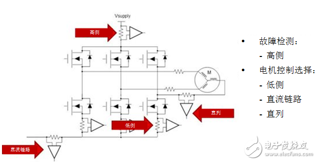
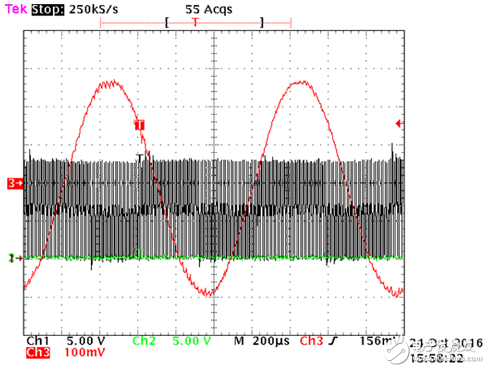
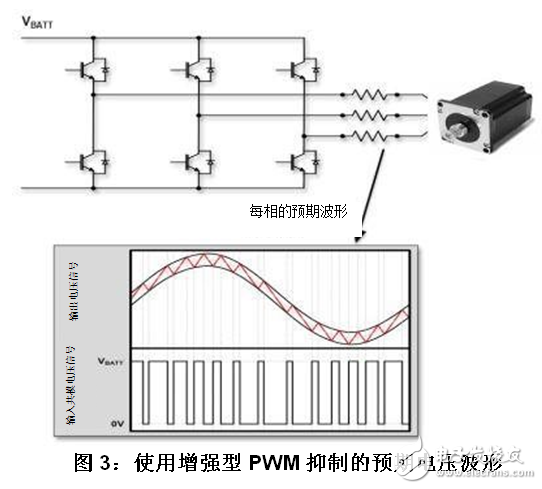
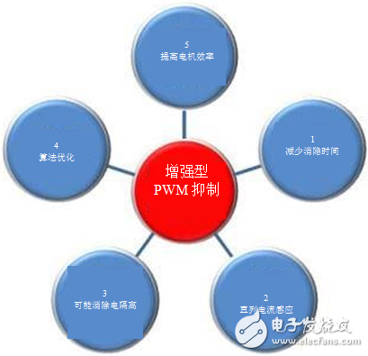
There are usually more than one way to solve a problem. Sometimes the most widely used method does not yield the greatest benefit. System designers of motor control projects use a variety of current measurement methods to ensure efficient motor operation and prevent possible damage. There are three main methods for measuring current in motor design. In this blog post, we will review these three methods and share the five advantages of in-line motor current sensing using enhanced pulse width modulation (PWM) suppression. As shown in Figure 1, there are basically three different ways to measure the current in a three-phase motor drive system: low side, DC link, and inline measurement. Figure 1 shows a conventional three-phase PWM inverter that uses three pairs of power MOSFETs (insulated gate bipolar transistors IGBTs are also common) to drive DC motors. The figure also includes high side current sensing, which is typically used in the case of significant errors, such as when the ground circuit is shorted. Figure 1: Various current sensing methods for three-phase motor drive systems Many designers use the first two methods (low-side, DC link, and various combinations) because standard current sensing solutions are readily available—typically with fast response times, higher bandwidth, fast output slew rate, and low total Mode input voltage. However, these existing products can sense phase current through low-side or DC links, but that doesn't mean the simplest solution. The dominant idea of ​​measuring current in these ways is to attempt to replicate the current that is driven into the motor windings. This replication happens in software; it can be widely involved, but not precise enough. The in-line current sensing method seems to be the most reasonable because it is the current to be measured. But there is a problem with this approach. The PWM signal that drives the MOSFET or IGBT causes severe damage to the current sense amplifier. The common mode signal at the sense resistor is driven from the supply voltage to ground with very fast transient switching characteristics, while the current sense amplifier attempts to measure the small differential signal of the sense resistor itself. Figure 2 is an oscilloscope screenshot of a sinusoidal phase current (red waveform) generated by a PWM inverter. In this case, the PWM frequency is 100 megahertz (MHz) and is provided by the LMG5200 GaN half-bridge power stage (see TI Design at the bottom for more details). It should be noted that the fast switching signal is the signal received by the in-line current sense amplifier when measuring the phase current. It's like in the case of a hurricane, when the cup floats on the sea and tries to measure the liquid in the cup. No wonder most designers will consider using low side sensing! Below we will introduce another method. Figure 2: Measuring phase current during fast common mode transients Before describing the potential advantages, explain the enhanced PWM suppression. Enhanced PWM Suppression is an active circuit that stabilizes the output voltage faster than conventional methods. Because current sense amplifiers can detect input common-mode signals with fast transitions, these disturbances are minimized when the device output propagates. Another way to reduce these disturbances (which the designer is affectionately called "ringing") is to use a high-bandwidth amplifier (in the MHz range) to stabilize the output as quickly as possible, but the cost of this method can be expensive. Figure 3 shows the output voltage signal for each phase without noise introduction. The red waveform is a signal indicating that the power transistor is copied to the motor as close as possible to the sinusoidal waveform, which is electronically commutated. The current sense amplifier will experience an input common-mode voltage signal from the supply rail (eg, VBATT = 48V) to ground. Advantage 1: Reduce the blanking time Common mode PWM transient suppression allows for less "ringing" at the output of the current sense amplifier. Waiting for the voltage signal to stabilize is a major drawback, especially for systems that require low busyness (≤10%) because the time to measure the current is reduced (commonly known in the industry as blanking time). Advantage 2: Inline current sensing Combined with a high common-mode input voltage, enhanced PWM rejection monitors in-line current. As discussed earlier, the robustness of current sense amplifiers is a must because of the harsh environment they are exposed to. In addition to this requirement, the amplifier must also have high AC and DC accuracy to provide system designers with accurate current sensor measurements. You can use the INA240 in TI TechNote to read more information on in-line motor current sensing. Advantage 3: Possible elimination of electrical isolation Another advantage of enhanced PWM rejection is subtle but important. With enhanced PWM rejection, designers do not need to use isolated current sensing devices when galvanic isolation is not required by the system. Customers often use isolation devices to decouple the noise generated by the PWM signal as it passes through the sense resistor. Decoupling is no longer required with enhanced PWM rejection. Advantage 4: Algorithm Optimization I mentioned this advantage before – algorithm optimization. With enhanced PWM suppression, there is no need to copy or calculate the phase current because the ready-made answer is available directly. The motor can be run efficiently with very little software. Advantage 5: Improve motor efficiency I want to talk about the last advantage - improving motor efficiency, which is the most important thing for designers. Motor manufacturers and motor drive system designers are always looking for ways to improve motor efficiency. High AC and DC accuracy, fast output response and reduced blanking time allow the motor to operate with the highest possible efficiency. Accurate timing control of the multiphase motor minimizes blanking time to maximize motor efficiency. Figure 4 shows the five advantages. Figure 4: Five Advantages of Enhanced PWM Suppression Scooter Charger,Fast Charger For Scooter,Scooter Battery Charger,Smart Charger For Scooter HuiZhou Superpower Technology Co.,Ltd. , https://www.spchargers.com