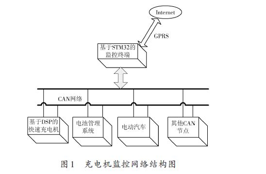
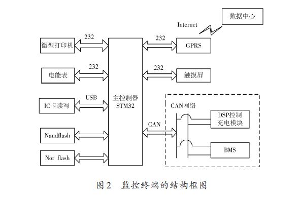
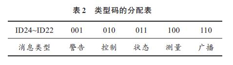
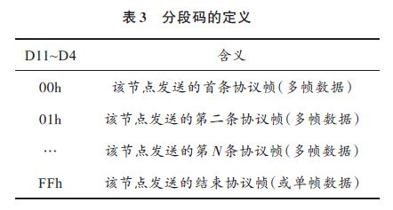
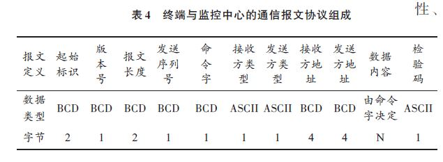
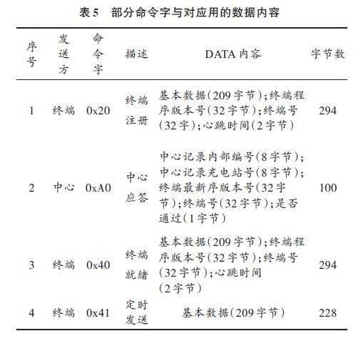
0 Preface With the country's strong support for new energy technologies, electric vehicles have gradually become the target of the country's vigorous development in the new energy vehicle industry, and electric vehicle charging stations and fast chargers are indispensable service infrastructure after large-scale electric vehicles. one. A large number of off-board intelligent fast chargers for electric vehicles distributed in various residential quarters and parking lots will become mainstream in order to achieve efficient, safe and intelligent management. In view of the unattended operation of the current fast charging group, this requires that the fast charger must have higher reliability and automation, more complete functions, and remote maintenance. In this way, distributed, modular and intelligent become the development direction of fast chargers, and high-performance, low-cost charger monitoring terminals are the key technologies. In order to optimize the resource utilization and management of multiple chargers in the management area, it is inevitable that the monitoring terminal interacts with the Internet. 1 Overall plan for monitoring the network As shown in the monitoring network structure diagram of the charger of Fig. 1, the monitoring terminal serves as an important gateway between the charger and the monitoring center. Its effective communication links are: monitoring center - monitoring terminal; monitoring terminal - charger (or battery management system (BMS), electric car, etc.). Through the monitoring terminal as a medium, the establishment of a communication link between the monitoring center and the charger and the electric vehicle is realized. The terminal communicates with the charger, the BMS and the electric vehicle through the CAN network, collects the data information of the relevant node and stores it, and feeds the relevant information to the charger. The charger realizes intelligent charging of the electric vehicle battery based on the relevant information. The terminal communicates with the monitoring center through GPRS connection. The terminal transmits the relevant data of the charger, battery and electric vehicle back to the monitoring center. The monitoring center realizes the remote control and real-time monitoring function of the charger, and records the operation and failure of the charger. Happening. The owner can check the current idle charger location by the monitoring center to make full use of resources. 2 monitoring terminal function module 2.1 Overall design of the monitoring terminal The monitoring terminal is a bridge connecting the monitoring center and the charger. The overall design structure is shown in Figure 2. The monitoring terminal is mainly composed of the core module of STM32ZGT6 of Cortex-M3 core, data acquisition module (CAN network), user charging interactive information module, data storage module, real-time clock module and GPRS communication module. It consists of 6 parts. The terminal uses the STM32ZGT6 microprocessor chip of the Co-tex-M3 core. The MCU has a wealth of on-chip hardware resources, including a CAN 2.0B controller, and up to four serial ports to meet the needs of the terminal CAN and GPRS network interfaces. The working process of the monitoring terminal is as follows: the user billing module reads the user information and selects the charging mode, and sends a corresponding charging command to the charging module through the CAN network; at the same time, the monitoring terminal reads the key data frame in the CAN network, such as the running status of the charger, etc. And save the data in NandFlash. The current charging user information and operating parameters such as the charger are periodically sent to the monitoring center via GPRS. The monitoring terminal can print the user's balance or charging credentials according to the needs of the user. 2.2 CAN bus module In order to better ensure the reliable transmission of the CAN bus, the system defines a common application layer CAN bus protocol. The message ID of the CAN 2.0B protocol is mainly allocated and defined. As shown in Table 1. (1) Priority determination. The CAN protocol specifies that the smaller the message ID, the higher the priority of the message. When competing for the bus, the packets with the highest priority are sent preferentially, and the packets with the lower priority are competing for the bus. The algorithm of CAN bus competition is very efficient and is a non-destructive competition [3]. Because the CAN protocol specifies that the identifier is high to low, the first seven bits cannot be all dominant. Therefore, the priority 1111b is reserved, so the system has 15 priority levels. (2) Type code. The protocol will specify the type of message from ID24~ID22. In this system, the types of messages used are: control, status, measurement, warning and broadcast. The specific allocation according to the type code is shown in Table 2. (3) Source address. The protocol stipulates that ID12~ID16 are source addresses, and ID17~ID21 are destination addresses, which in turn identify each receiving node and sending node of the message. The 5-bit address bit retains 11111b as the broadcast address, and 31 control nodes can be identified to meet the monitoring requirements of the electric vehicle charger. In this system, 00000b is defined as a monitoring terminal, 00001b is a charger node, and 00010b is a battery management system (BMS) node. (4) Segment code. Due to the different amount of data sent by different nodes, a data frame may not be able to send the data collected from the bottom layer once (that is, more than 8 bytes). In the protocol, ID11~ID4 are defined as segmentation codes, as shown in Table 3. In Table 3, the data frame of a node starts with the segment code 00H and ends with FFH, and supports up to 256 & TImes; 8 bytes of data. If the node has only one frame of data, the definition FFH is also a single frame of data. For example, the BMS node includes information on the total battery pack voltage, the total battery pack current, the battery pack SoC, the temperature of each battery pack (nine), and the battery pack status. Each data occupies 2 B. Obviously, a data frame cannot send all the information of the node, so it must be sent in multiple frames. 2.3 data transmission module The terminal is connected to the Internet through a serial port external Zhou Ligong GPRS module (ZWG-23A). After surfing the Internet through the GPRS network, after connecting to the server, the data is sent to the server periodically according to the communication protocol. According to the "Shenzhen Electric Vehicle Charging System Technical Specifications" standard document, the agreement consists of the message start identifier, version number, command word, message length, data content, check code, etc., the specific format is shown in Table 4. . (1) Initial identification. Set to 0xFAF5 to wake up the receiver to receive data. (2) The length of the message. Is the total length from [send serial number] to [data content]. (3) Check code. It is a carry-free accumulation sum from [starting mark] to [data content]. (4) Receive (send) party type and address. The value of the monitoring center is "Business Service Platform", its value is 1, its address is a unique address under this type code; the type of the terminal is "scheduling terminal", its value is 255, and the address is under this type. A unique address. (5) Data content and command words: Different command words determine the composition of the content of the data carried by the message and the number of bytes occupied. Data content is typically a combination of one or more data objects, or it can be empty. In the case that the sender responds abnormally or not, each data message is sent at most six times, each time interval is 30 s. The data content is different according to the command word, and the data object is different. The communication between the terminal and the monitoring center includes four stages: terminal registration, center response, terminal ready, and timing transmission. Some command words and corresponding data contents are shown in Table 5. With the advancement of technology, LED technology has been applied to projectors. There are many good domestic LED projector manufacturers in the market. For example, Shenzhen Resources has perfectly combined this technology with DLP technology to make it portable and compact. Because of its low power consumption and heat generation, it is more widely used in life and in personal business. The same goes for LED hotel projectors. portable led projector,led home theater projector,led holiday projector,led room light projector,led 4k projectors Shenzhen Happybate Trading Co.,LTD , https://www.happybateprojectors.com