Generator automatic start and stop circuit diagram Daquan (contactor / pump start / stop / motor)
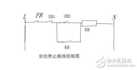
Start stop circuit diagram _ start stop button wiring diagram: FR---thermal relay, SB 1--jog stop switch, SB2-- jog start on, off KM--contactor coil KM--contactor normally open contact
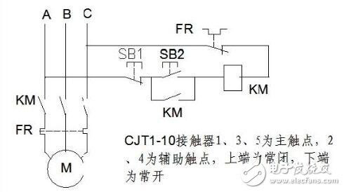
Working principle circuit diagram
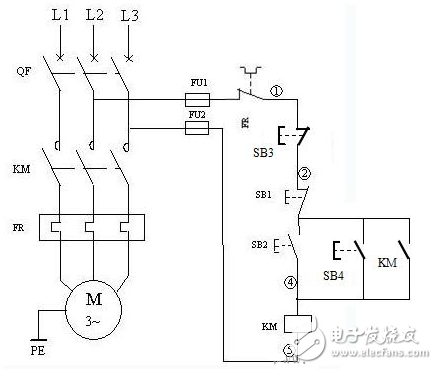
The circuit diagram is the control circuit of the motor 2. In the figure, SB1 and SB2 are set to start and stop control buttons; SB3 and SB4 are B start and stop control buttons, and 2 sets of buttons jointly control motor M.
The characteristics of the multi-ground control circuit are: the stop button is connected in series, and the start button is connected in parallel.
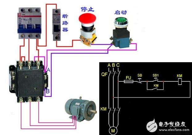
Circuit working principle
Start: press the start button SB2 or SB4 → KM coil of the two places (any) to get the electric pull-up → its normally open auxiliary contact closes the self-locking → its main contact closes the motor main circuit → the motor M runs.
Stop: press the two buttons (arbitrary) stop button SB1 or SB3 → KM coil power loss release → its normally open auxiliary self-locking contact opens the self-locking loop → its main contact release disconnects the motor main circuit → motor M stops Running.
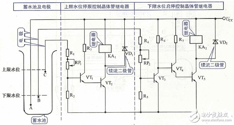
Generator automatic start and stop circuit diagram (3)The pump start and stop control circuit diagram is shown in the figure.
Fast Recovery Diode (FRD) is a semiconductor diode with good switching characteristics and short reverse recovery time. It is mainly used in switching power supplies, PWM pulse width modulators, inverters and other electronic circuits as high-frequency rectifier diodes. Free-wheeling or damper diodes are used. The internal structure of the fast recovery diode is different from that of an ordinary PN junction diode. It belongs to a PIN junction diode, that is, a base region I is added between the P-type silicon material and the N-type silicon material to form a PIN silicon wafer. Since the base area is thin and the reverse recovery charge is small, the fast recovery diode has a short reverse recovery time, a low forward voltage drop, and a high reverse breakdown voltage (withstanding voltage).

Fast Recovery Stud Diode,Stud Type Fast Recovery Diode,Fast Recovery Diode,Stud Rectifier Power Diode
YANGZHOU POSITIONING TECH CO., LTD. , https://www.pst-thyristor.com