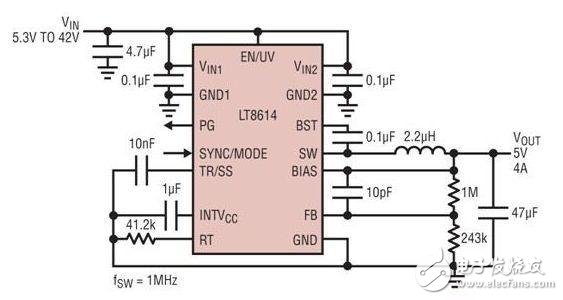
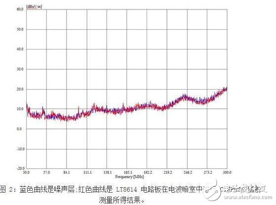
Everyone knows that the layout of a printed circuit board determines the success or failure of all power supplies, determining functionality, electromagnetic interference (EMI), and performance when heated. Switching power supply layout is not magic, not difficult, but in the initial design stage, it may often be overlooked. However, because both functional and EMI requirements must be met, arrangements that are beneficial to the stability of the power supply are often beneficial in reducing EMI emissions, so it is better to do it later. It should also be mentioned that designing a good layout from the start does not incur any cost, and in fact saves money because there is no need for EMI filters, mechanical shielding, time-consuming EMI testing, and modification of the PC board. In addition, when multiple DC/DC switching mode regulators are connected in parallel to achieve current sharing and greater output power, potential interference and noise issues may deteriorate. If all regulators operate at similar frequencies (switches), the total energy produced by multiple regulators in the circuit is concentrated at one frequency. The presence of this energy can be a concern, especially if the PCs and other ICs on other system boards are close together and are susceptible to this radiant energy. This problem can be particularly troublesome in automotive systems because automotive systems are densely packed and often close to audio, RF, CAN buses, and various radar systems. Respond to switching regulator noise radiation problem In automotive environments, switching regulators are often used in places where heat dissipation and efficiency are important to replace linear regulators. In addition, the switching regulator is typically the first active component on the input power bus and therefore has a significant impact on the EMI performance of the entire converter circuit. There are two types of EMI radiation: conductive and radiative. Conducted EMI depends on the wires and circuit traces that are connected to a product. Since the noise is limited to a particular terminal or connector in the design of the solution, then with the good layout or filter design described above, it is often possible to ensure compliance with conducted EMI requirements early in the development process. However, radiative EMI is another matter. All components carrying current on the board radiate an electromagnetic field. Each trace on the board is an antenna, and each copper plane is a resonator. In addition to a pure sine wave or DC voltage, any signal produces noise that covers the entire signal spectrum. Even after careful design, the designer will never really know how severe the radiated EMI will be before the system is tested. And it is not possible to formally conduct a radiated EMI test until the design is basically completed. The filter can attenuate the intensity at a certain frequency or over the entire frequency range to reduce EMI. Part of the energy is transmitted through the space (radiation), so metal shields and magnetic shields can be added to attenuate. The portion of the PCB trace (conducted) can be controlled by adding ferrite beads and other filters. EMI cannot be completely eliminated, but can be attenuated to acceptable levels for other communications and digital components. In addition, several regulatory agencies enforce standards to ensure compliance with EMI requirements. New input filter assemblies using surface mount technology perform better than through-hole assemblies. However, this improvement is offset by an increase in the switching frequency of the switching regulator. Faster switching produces higher efficiency, shorter minimum on and off times, and therefore higher harmonic components. With all other parameters such as switching capacity and switching time remaining constant, EMI is degraded by 6 dB for every doubling of the switching frequency. Broadband EMI behaves like a first-order high-pass filter, which increases 20dB of radiation if the switching frequency is increased by a factor of 10. Experienced PCB designers will design the hotspot loop to be small and keep the shielded formation as close as possible to the active layer. However, the device pinout configuration, package construction, thermal design requirements, and the package size required to store sufficient energy in the decoupling component determine the minimum size of the hotspot loop. To complicate matters, in a typical flat-panel printed circuit board, magnetic or transformer-type coupling above 30 MHz between traces will offset all filter efforts because the higher the harmonic frequency, the unwanted magnetic coupling Become more effective. A new solution to these EMI problems The solution to a reliable and truly EMI problem is to place the entire circuit in a shielded box. Of course, doing so increases costs, increases board space requirements, makes thermal management and testing more difficult, and results in additional assembly costs. Another method that is often used is to slow the edges of the switch. Doing so can produce an undesirable result, which is to reduce efficiency, increase the minimum on and off times, and generate related dead time, which is detrimental to the speed that the current control loop can achieve. Linear Technology recently introduced the LT8614 Silent Switcher regulator, which eliminates these drawbacks by eliminating the need for a shielded box and providing the desired shielding effect. See Figure 1. The LT8614 also features world-class low IQ with an operating current of only 2.5? A. This is the total supply current that the device consumes during no-load regulation. The device's ultra low dropout voltage is limited only by the internal top switch. Unlike other solutions, the LT8614's RDSON is not limited by the maximum duty cycle and minimum off time. The device skips the switch-off period when a dropout occurs and only performs the minimum required turn-off period to keep the internal top-switching boost-level voltage continuously available, as shown in Figure 6. At the same time, the LT8614's minimum input operating voltage is typically only 2.9V (up to 3.4V), allowing the device to provide a 3.3V rail with a dropout voltage. The LT8614 is more efficient than the LT8610/11 at high currents because of its small overall switching resistance. The device can also be synchronized to external frequencies from 200kHz to 3MHz. The device's AC switching losses are low, so it can operate at high switching frequencies with minimal loss of efficiency. A good balance can be achieved in EMI-sensitive applications, such as those common in many automotive environments, and the LT8614 can operate at frequencies below the AM band (to achieve even lower EMI) or above the AM band. jobs. In settings with a working switching frequency of 700kHz, the standard LT8614 demo board does not exceed the noise floor of the CISPR25 - Calls 5 measurement. The measurement results shown in Figure 2 were obtained in an anechoic chamber and under the following conditions: 12Vin, 3.3Vout/2A, and a fixed switching frequency of 700kHz. . The LT8614 and LT8610 were tested to compare the LT8614 with Silent Switcher technology to the LT8610, another state-of-the-art switching regulator. The test was performed in a GTEM cell and the measurement of both devices used a standard demo board with the same load, input voltage and the same inductor. Zinc Aluminum Alloy Wire, zinc is the matrix, through different aluminum content to meet the needs of different customers, and the use of advanced production technology, strict quality control, surface and inner quality is good and stable, with good mechanical properties. Using in film capacitor surface spray Zinc Aluminum Alloy Wire,Blasting Materials,Anti-Corrosion Spraying Material,Ductile Iron Pipe Shaoxing Tianlong Tin Materials Co.,Ltd. , https://www.tianlongspray.com