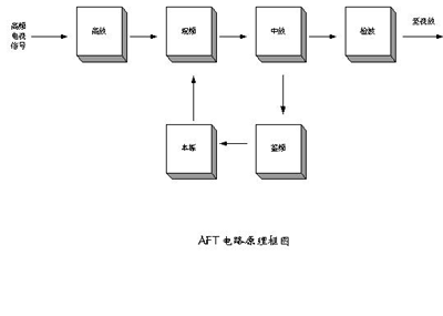
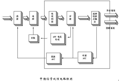
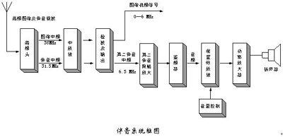
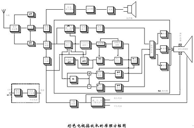
A: The main difference between color TV and black-and-white TV is that color TV has one more color decoding circuit and kinescope than black-and-white TV. The rest is basically the same. All are composed of high-frequency tuner, intermediate frequency circuit, video circuit, audio circuit, scanning circuit, power supply circuit and other circuits. The main working principles of each part are briefly described below. 1) High frequency tuner (high frequency head) High frequency tuner is also called channel selector, commonly known as high frequency head. In terms of structure, there are two types of tuner. One is a mechanically tuned tuner, which selects channels by changing the inductance (switching type, turntable type); the other is an electrically tuned tuner. The DC voltage changes the capacitance (varactor diode) in the loop for channel selection. The mechanically tuned tuner is easy to operate and stable, but it is bulky and is rarely used now. The advantages of the electric tuning high-frequency head are that it has no mechanical contacts and long life. The frequency is continuously adjustable in the band range, but the frequency position is not fixed, and it needs to be temporarily adjusted when changing the station. To avoid this trouble, a multi-channel preselector must be added. The local frequency of the electronic tuner is susceptible to temperature changes and must be corrected with an AFC circuit. At present, the high-frequency heads used in color TVs are mostly electric tuned high-frequency heads, and are basically controlled by a microcomputer. The electric tuning high-frequency head is generally composed of several parts such as the input loop, high-frequency amplifier, local oscillator and mixer, and simultaneously performs high-amplifier automatic gain control (AGC) and automatic frequency fine-tuning (AFT) control. The role of the mixer is to convert the image high-frequency signal (fp) and the audio high-frequency signal (fs) into their fixed image intermediate frequency (fpI 38MHz) and the first audio intermediate frequency (fsI 31.5MHz) signal, and then send it to the intermediate frequency amplifier Further amplify, while the amplitude and instantaneous frequency of the high-frequency television signal amplitude modulation wave representing the image and sound information are unchanged. The radio frequency TV signal received by the TV receiver enters the high-frequency tuner, and the frequency is selected through the LC tuning loop in the input circuit, the useless signal is removed, the useful signal is selected, and then amplified by the high frequency, and the local oscillator circuit The sent high-frequency sine wave signal is sent to the mixer together for mixing. The function of the mixing circuit is to make two high-frequency signals beat to produce a beat signal, and then select the beat signal through the LC circuit to obtain a TV signal that becomes an intermediate frequency, the frequency of which is higher than the original input. The frequency of the frequency signal is very low, but the information carried in the signal has not changed at all. Changing the oscillation frequency of the local oscillator circuit (changing the reverse voltage of the varactor diode in the LC loop) can change the frequency of the received signal, that is, channel selection. a) AFT circuit The AFT circuit is generally called an automatic frequency fine-tuning circuit, which is basically similar to the working principle of a general phase-locked loop circuit, except that the error control signal of the phase-locked loop circuit is taken from the phase discrimination circuit, and the error control signal of the automatic frequency fine-tuning circuit It is a frequency discrimination circuit taken from an intermediate frequency amplifier. The local oscillator in the electric tuning tuner is a voltage-controlled oscillator. Changing the control voltage can change the tuning frequency, and the error voltage output from the frequency discrimination circuit of the intermediate frequency amplifier is also added to the input terminal of the control voltage of the voltage-controlled oscillator. It can realize automatic frequency fine-tuning, so that the color TV receiver can receive color TV signals more stable and will not drift with environmental changes. 2) Intermediate frequency circuit The main function of the intermediate frequency circuit is to amplify the intermediate frequency television signal, and the other is to demodulate the video signal of the intermediate frequency television signal and beat out the 6.5MHz second sound intermediate frequency FM signal. The IF TV signal is a high-frequency signal with a fixed frequency. China's standards stipulate that the image IF is 38MHz and the sound IF is 31.5MHz. The IF is only relative to the input high-frequency signal. The amplitude of the intermediate frequency signal output by the tuner is very small, and there are still many clutters, which need to be filtered and then further amplified. Intermediate frequency signal clutter filtering generally uses surface acoustic wave filters, the principle of which is to transform an electrical signal into a sound wave through a transducer. The sound wave propagates in a medium similar to a tuning fork structure to produce resonance, and the amplitude of the generated resonance signal will overlap Plus, the amplitude of the non-resonant signal will be subtracted, and the resonant sound wave is finally converted into an electrical signal by the transducer. In fact, the transducer is a piezoelectric ceramic sheet that we are familiar with. The surface acoustic wave filter is made of a lot of acoustic wave filters similar to the tuning fork structure on a silicon chip. Its performance can be superimposed on each other to ensure that the surface acoustic wave filter has very high selectivity and 6 MHz bandwidth. The output signal after the intermediate frequency amplification is more than 1 volt, and then video detection. The function of the video detection and output circuit is to take out the video modulation signal from the image IF AM signal output by the IF amplifier, that is, the video full TV signal, and send it to the image channel; make the image IF (38MHz) and the sound IF (31.5MHz) pass detection After the beat, a 6.5MHz second sound IF FM signal is generated and sent to the sound channel; the third role is to output a DC signal voltage (AGC) that reflects the strength of the video image signal. Gain is automatically controlled. The principle of video detection is very simple, it can be realized by a high-frequency rectifier diode, but it is rarely used now, and the synchronous detector is used. The working principle of the synchronous detector is to multiply two signals with the same phase and switch power supply. The principle of synchronous rectification is basically the same. The advantage of the synchronous detector is that the signal distortion is relatively small. The signal obtained after synchronous detection is a video signal and a second sound signal, or it is a composite signal, in which there are multiple signal components, such as a synchronization signal and a color signal. The gain of the intermediate amplifier also needs AGC control to ensure that the amplitude of the output signal is basically stable. 3) Video circuit One of the functions of the video circuit is to amplify the video signal, and the other is to separate multiple signal components. The video signal is a general term for image signal, synchronization signal, color signal, and second sound signal. After the video signal is amplified by the pre-amplifier to make the signal output amplitude basically reach the standard level of about 1 volt, the video signal is sent to the corresponding separation circuit for signal separation. The video processing circuit mainly includes: a luminance signal processing circuit, a chrominance signal processing circuit, and a decoding primary color matrix circuit. The video signal generally refers to the color full TV signal (FBAS), which is formed by the superposition of the black and white full TV signal and the chrominance signal. It is combined with the high frequency sound signal and is called the color full TV RF signal, and uses the residual sideband. send. The color full TV signal is composed of a luminance signal with a bandwidth of 6 MHz and a chrominance signal with a bandwidth of 2.6 MHz, which are superimposed in a spectrally interleaved manner, and a composite synchronization signal, a composite blanking signal, and a color burst signal are added. The luminance signal processing circuit can also be called a luminance channel. The second audio intermediate frequency signal is removed from the video signal via a 6.5MHz notch filter, and the color subcarrier signal is removed using a 4.43MHz notch filter. Luminance signal (Y signal), if it is a black-and-white TV, the luminance signal can be sent to the cathode of the black-and-white kinescope for black-and-white TV image display after being amplified by the final-stage video amplifying circuit; Y is separated from the color full TV signal, after amplification and processing, it is made to reach the amplitude required for decoding the primary color matrix, and the color difference signals RY and BY resolved by the chroma channel are sent to the decoding matrix circuit to find the primary color Signals R, G, and B, respectively, stimulate the corresponding cathode of the color picture tube to achieve color reproduction; at the same time, complete color subcarrier suppression, automatic sharpness control, high frequency signal compensation (edge ​​trimming), DC level recovery, brightness and contrast adjustment , Automatic brightness limitation (ABL), brightness delay and synchronous separation. The chrominance signal is transmitted by quadrature modulation (amplitude modulation) of the 4.43MHz subcarrier, and its bandwidth is 1.3MHz. It is inserted into the high-frequency end of the luminance signal band in a spectrally interleaved manner. If it is not added in the luminance signal processing circuit Suppression, the chrominance signal is also amplified by the luma channel, causing the moire of the chroma signal to the luma signal. The color subcarrier suppression circuit is to set a 4.43MHz color load wave absorption circuit in the brightness channel to reduce this moire. Color televisions are compatible with black and white televisions, so color televisions also receive black and white television signals. In addition, the sensitivity of color televisions to receive color image signals is much lower than that of black and white television signals, and the clarity of color image signals It is also much less sharp than receiving black and white TV signals. The reason is that the bright and color separation circuits will damage the luminance signal, and the amplitude and high-frequency components of the signal will be reduced a lot. The 4.43MHz notch in the color subcarrier suppression circuit suppresses the color subcarrier and also puts the black and white TV signal The high frequency components around 4.43MHz are absorbed, which causes the image sharpness to decrease. The function of the automatic clarity control circuit is that when receiving normal color signals, the subcarrier suppression circuit works, and when receiving black and white TV programs or the signal is too weak, it automatically disables the subcarrier suppression circuit to restore the clarity of the black and white image to normal Level. High frequency signal compensation is also called contour correction circuit. Generally, a small part of the signal with the largest rate of change in the luminance signal is extracted using a differential circuit. After amplification and phase compensation, it is mixed with the original luminance signal and superimposed, so that the image appears blacker at the edge of the transition. The whiter and whiter dividing line seems to tick an edge on the edge of the image. In this way, the outline of the image is more prominent, thereby improving the visual clarity. The function of the DC level recovery circuit is to recover the DC signal in the luminance signal, because the DC signal is lost in the transmission process, or the DC signal cannot be transmitted in the channel. The restoration of the DC signal is very simple, it is only necessary to embed the brightness signal at the level of 70% of the signal peak, and the 70% of the peak of the brightness signal is equivalent to the zero level of the image signal. The function of the contrast adjustment circuit is to change the gain of the brightness channel to change the contrast level of the image light and dark. The function of the ABL circuit is to avoid defocusing or damage to the kinescope caused by the excessive current of the kinescope beam for some reason. When the kinescope current reaches a certain value, the ABL circuit begins to function to control the beam current not to exceed the rated value. The function of the brightness delay line is to delay the brightness signal by about 0.6 microseconds. According to network theory, the delay time of a signal through a transmission system is inversely proportional to the bandwidth of the system, so the narrower the channel bandwidth, the longer the signal delay. The luminance signal bandwidth is 6MHz, while the chrominance signal bandwidth is 2.6MHz. Since the luminance channel bandwidth is wider than the chrominance channel, the time for the color difference signal to reach the decoded primary color matrix is ​​longer than the luminance signal. Causes the image color chrome phenomenon. Therefore, a brightness delay line needs to be added in the brightness channel so that the bright and color signals can reach the decoded primary color matrix synchronously. The amplitude of the synchronization signal in the video signal is about 30% higher than the amplitude of the image signal, so the synchronization signal can be easily separated by the amplitude comparison. Synchronous separation circuits generally use a capacitor to charge and discharge through a PN junction (or diode) of a transistor. The time constants are different, which will generate accumulated charge on the capacitor and hinder the input signal. Only the input signal has a high amplitude The signal can only pass when the voltage generated by the accumulation of charge on the capacitor, that is, the level comparison function, separates the synchronization signal. What is separated by the synchronization separation circuit is a composite synchronization signal, that is, a horizontal and vertical synchronization signal. The field sync signal needs to be separated from the peer sync signal. The PAL line scan is defined as 625 lines. In fact, 25 lines have no image content, which is called the line blanking signal, so it can be added in the first few lines of the 25 lines. Some bursts are used as field synchronization signals. After the integration of these pulse groups, a trigger pulse can be obtained, which is used to trigger the field oscillation synchronization. 4) Sound circuit The full TV signal is selected through the 6.5MHz bandpass filter to select the second sound intermediate frequency signal, and then sent to the limiting amplifier for amplification and limiting. The amplified signal is sent to the frequency discriminator for frequency modulation and demodulation, and the audio signal is then subjected to low frequency The amplifier amplifies and finally outputs power to the speaker, and the speaker can emit sound. The early frequency discrimination circuit used the bell-shaped resonance curve of the LC tuning loop to perform slope detection to demodulate the frequency-modulated signal, and the two LC tuning loops were combined to obtain an S curve. This method has been rarely used. At present, most frequency discrimination circuits use a method of multiplying the phase-locked loop signal and the input signal, that is, the phase-sensitive rectification method. The reason is also very simple, because the differential of the phase is the frequency. 5) PAL decoder Color TVs have one more PAL decoder in the circuit than black-and-white TVs. In addition, color TVs generally use a remote control to operate, so they use microcomputers to control various functions, so color TVs have more than black-and-white TVs. Good performance is also more complicated on the circuit and more and more functions. Here only some key technical principles are introduced, and other technologies will be introduced later. In the color TV principle block diagram, in addition to the addition of a PAL decoder, because color TVs generally use electrically tuned high-frequency heads, color TVs generally have an automatic frequency control (AFC) circuit, also known as automatic Frequency trimming (AFT) circuit. The PAL decoder is composed of a luma channel and a chroma channel. The input signal of the PAL decoder comes from the pre-video amplifying circuit. The color signal component in the video TV signal is taken out by the 4.43MHz filter, and then the two orthogonal chrominance signal components u and v are further separated by the comb filter. Perform synchronous detection to obtain color difference signals (BY) and (RY). The switch control signal required for synchronous detection is the color subcarrier (4.43MHz), which is generated by the subcarrier phase-locked oscillator and the PAL switch. The output signal of the subcarrier phase-locked oscillator is synchronized by the color burst signal in the chrominance signal . In order to stabilize the output amplitude of the chroma signal, there is also an automatic color saturation control (ACC) circuit. In order to prevent the color TV from receiving black and white TV signals, the subcarrier phase-locked oscillator interferes with the image signal and improves the clarity. There is also an automatic decolorization control (ACK) circuit in the picture. When receiving black and white TV signals, or When the color signal is very weak or the demodulation subcarrier is abnormal, it can automatically close the chroma channel. The chroma channel mainly completes automatic gain control, chroma amplification, color saturation adjustment, subcarrier recovery, chroma signal demodulation, and automatic color elimination. The chrominance signal demodulation circuit demodulates the two color difference signals RY and BY from the color full TV signal, and the three primary color signals R, G, B are processed by the decoding matrix circuit together with the luminance signal Y. The function of the automatic chroma control circuit (ACC) is to dynamically adjust the chroma signal to stabilize its amplitude without causing the image to become dark and light. Therefore, the amplitude ratio of the chrominance signal and the luminance signal is kept unaffected by the fluctuation of the chrominance signal amplitude, and the color saturation distortion is avoided. The comb filter is the core part of the decoder. The main function is to use the correlation between the lines of the TV signal to separate the red and blue chrominance components u and v from the chrominance signal. Since u and v are 90 degrees out of phase, if the u or v signal is delayed by one-half cycle (or four-quarter cycle), and then the output signal is added and subtracted from the input signal, you can get two sets of new signals, That is, u and v are completely separated. Because the amplitude-frequency characteristic of the u and v signals separated and output by the delay line is comb-shaped, it is also called a comb filter. In practical applications, a line of delay lines is generally used to replace the two-by-one cycle delay line. Therefore, the delay line in the PAL decoder has two functions, one is used as a comb filter, and the other is used as a line of delay. The early line of delay line used ultrasonic glass delay line, and now basically has been integrated circuit. In the luma channel, in order to suppress the interference of the chroma signal to the luma signal, a 4.43MHz notch filter is used to absorb the chroma signal. The function of the automatic sharpness control (ARC) circuit is to remove the sub-carrier trap when receiving black and white TV signals to improve the sharpness of the image. In order to compensate for the delay of the narrow-band chrominance signal, the brightness delay line is set in the "bright color ghosting" diagram. The function of the decoding matrix is ​​to transform the luminance signal Y and the color difference signals (RY) and (BY) into three primary color signals of R, G and B, and finally through the final stage of video amplification, the signal is added to the three R, G and B kinescope The cathode controls the luminosity of the kinescope, and coupled with the function of the scanning circuit, the active color TV image can be displayed on the TV fluorescent screen. 6) Scanning circuit The composite synchronization signal is directly fed into the line-locked-loop oscillation circuit to obtain a line-scanning oscillation signal synchronized with the synchronization signal, and then amplified by the line-scan power, the output power is sent to the horizontal scanning deflection coil on the kinescope, which can be generated in the coil The horizontal sawtooth wave current generates a deflection magnetic field in the horizontal deflection coil. The magnetic field will generate a Lorentz force on the electron beam, deflect the electron beam accordingly, and generate an electronic scanning line. Display TV image. At the same time, the line output transformer can also obtain the corresponding high and medium voltage power supply, and provide the required voltage of the kinescope high voltage anode, focusing pole, acceleration stage and so on. The scanning voltage output by the horizontal scanning circuit is a square wave, and the voltage drop generated by the internal resistance of the deflection coil is compensated by a magnetic saturation inductor. The scanning voltage output by the field scanning circuit to the field scanning deflection coil is a trapezoidal voltage wave, and the sawtooth part is used to offset the voltage drop generated by the internal resistance of the deflection coil. 7) Power circuit The AC 220V mains is rectified and filtered, then the switching power supply is used for DC / AC conversion, and then the secondary output of the switching power transformer is used, and then rectified and filtered to obtain various DC voltages required by the TV. This switching power supply can be isolated between cold and hot ground to ensure personal safety. Follow WeChat Download Audiophile APP Follow the audiophile class related suggestion '+ data.data.username +' '; dom + =' The High Power Battery Pack is mainly used in various vehicles, ships, aircraft and other internal combustion engines, lighting, energy storage, uninterrupted power supply, mobile communication, portable electric tools, electric toys.there are some differences compared with other normal battery .
3.High Power Battery pack can discharge at higher instantaneous current than normal Lithium Battery Pack
High Power Battery Pack High Power Battery Pack,High Power Battery,Battery Pack,Lithium Polymer Battery YFJ TECHNOLOGY (HK) CO.,LIMITED , http://www.yfjpower.com What is the difference between a color TV and a black and white TV? What are the main circuits? 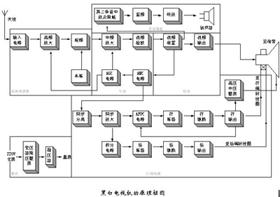
At the same time, in order to enable the TV to have a relatively stable signal output and not run when receiving strong and weak signals, the amplifier in the high-frequency tuner is subject to automatic gain control (AGC) voltage control, and the tuning frequency is subject to Automatic frequency fine-tuning (AFT) control. 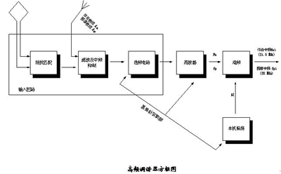


'+ data.username +'
'+ data.username +'
'; dom + ='
'; $ (' # follow_list '). append (follow_user);} if (data.status == "failed") {alert (data.msg);}});} else {// Unfollow if ($ ( this) .attr ('id') == 'cancelFollow') {$ .post ('/ d / user / cancelFollow', {tuid: article_user_id}, function (data) {// Data format returned: if (data .status == "successed") {follow_wrap.html ('Follow'). attr ('id', 'follow'). css ('background', '# f90'); $ (". followNum strong"). html (-getFollowNum); $ ('# follow_list .face'). each (function () {var target_uid = $ (this) .attr ('data-uid'); if (target_uid == now_uid) {$ ( this) .remove ();}})} if (data.status == "failed") {alert (data.msg);}}); return false;}}});});}); / * var myface = "{$ _super ['uid'] | avatar}"; var myname = "{$ _super ['username']}"; var article_id = {$ article ['id']}; var article_user_id = {$ article ['mid']}; // Article author ID $ (function () {<notempty name = "clearnum"> // Reduce the number of reminders var count = parseInt ($ ("# noticeCount"). html ()); count = count-{$ clearnum}; $ ("# noticeCount"). html (count); if ( count
1.properties
High power Lithium Battery is a battery that powers a vehicle, usually compared to a small battery that powers a portable electronic device. And normal lithium battery is a kind of anode materials for lithium metal or lithium alloy, using nonaqueous electrolyte solution of a battery, and Rechargeable Battery lithium ion battery and lithium ion polymer battery is not the same
2.discharge power
a 4200 mah high power lithium battery can discharge all power in just a few minutes, but normal lithium battery could not do that completely, so normal lithium battery discharge ability cannot be compared with the high power lithium batteries entirely. The biggest difference between high power lithium battery and onormal lithium battery lies in its high discharge power and higher energy. Since high power lithium-ion batteries are mainly used for automotive energy supply, they have higher discharge power than ordinary batteries.

[Photo] TV knowledge quiz (2)
Color full TV signal frequency city map
Interesting and informative information and technical dry goods
Create your own personal electronic circle
Lock the latest course activities and technical live broadcast
comment
Publish
[Photo] Automatic switch of TV sound transmitter
Published on 2006-04-15 20:39 • 230 views