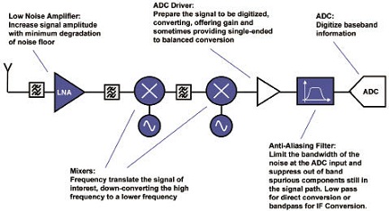
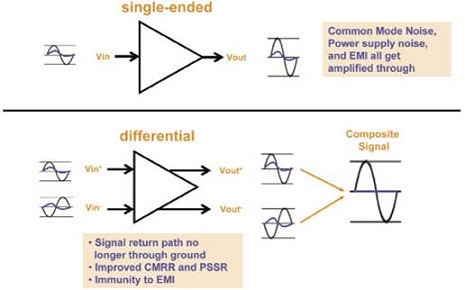
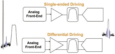
What are the related technologies of differential circuit design in communication applications? First, compare single-ended and differential signals, then briefly introduce some factors that need to be considered in the receiver's signal chain and system performance, and then you will find the advantages of differential applications . Comparing with single-ended applications from the perspective of driving ADCs, we will find that differential applications will be easier to achieve higher data rates. Finally, we will return to the system design level and summarize the benefits of differential applications. Single-ended and differential signals Let's talk about the concept of single-ended and differential signals first, everyone knows this well. Here we use another way to express, we can divide the signal into an unbalanced signal or a balanced signal, a single-ended signal belongs to an unbalanced signal, because it is a single-sided signal, so it is relatively speaking, there is no Balanced signal pairs generally produce higher harmonic distortion than unbalanced signals. The differential signal is a balanced signal, and the differential pair generally has a common common mode level and a differential mode level with the same amplitude. When measuring differential signals or balanced signals, what we care about is the difference between the positive and negative input signals. The harmonic distortion caused by this balanced signal is relatively small. System-level design On the other hand, when the communication system is applied, we see a signal chain of a general superheterodyne receiver. Figure 1 shows the signal chain of a general superheterodyne receiver. A low-noise amplifier is connected behind the antenna. , Used to amplify the signal and suppress noise, and then use a two-stage mixer to downconvert the signal to a lower frequency, during which we will add an appropriate filter to filter out noise and harmonics outside the useful signal band, and then drive ADC buffer op amp. This is the main issue we are discussing today. The main purpose of this level of op amp is to adjust the level range of the signal, improve the driving ability, and sometimes also as a conversion between single-ended differential. Before entering the ADC, we need to add an anti-aliasing filter, and finally use the ADC to perform analog-to-digital conversion on the baseband signal. We see that if the system wants to achieve a higher dynamic range, excessive noise and harmonics cannot be introduced other than the signal. Figure 1 The signal chain of a universal superheterodyne receiver Let's take a closer look at some of the more noteworthy performance and indicators in a communication system. Before we compare single-ended and differential signals, we need to understand some of the issues to be considered in system-level design. So, what kind of design is a better RF system design? First, the signal sensitivity is higher, which means lower noise, and the phase noise introduced by the clock is also lower. The input signal must have sufficient driving capability, and relevant indicators, such as high third-order intercept point and 1dB compression point. Then it is whether the performance of each module is good enough, whether it can distinguish the signal and noise better, whether the linearity is good enough, and so on. In addition, low power consumption and low cost are considered. We say that differential signal chains have many advantages over single-ended signals. Because it is a differential-mode signal, two differential signals are output. In fact, the amplitude of the differential-mode signal output is relatively doubled. In other words, under the same output range, the operating voltage will be lower. In this way, in applications requiring low harmonic distortion, sufficient amplitude margin can be guaranteed. The characteristic of the odd system similar to the odd function can eliminate the even harmonic terms in the system, that is, the 2nd, 4th, 6th harmonics, etc., the harmonics at these frequency points will be very small compared to the odd harmonics Can't even see it. Finally, because the return path of the signal is no longer a ground plane, the signal is less sensitive to the influence of the ground plane or the power plane, thereby reducing the introduction of noise coupling and achieving better anti-electromagnetic interference effects. As shown in Figure 2, single-ended signals are more sensitive to common mode noise, power supply noise, and electromagnetic interference, and the op amp will amplify these noises to some extent. The differential signal, because the signals on both sides itself form a current loop, suppresses common mode noise and interference, and only effectively amplifies the differential mode signal. Through derivation, we can also see the odd-order characteristics of differential amplification. Ideally, we can only see the fundamental and odd-order harmonics on the spectrum. Here we only give the conclusion. It is worth noting that the third harmonic and the third-order intercept point caused by it. IP3 is the theoretical input power at the intersection of the fundamental wave and the third-order distortion output curve. It is a description of the linearity of the amplifier. Important indicators: In the design of communication systems, the driving, extraction and loading of useful signals on the ADC input is a critical issue. For high-precision system design, appropriate selection of devices and interface methods is required. We will give you a few examples, but before you know, as shown in Figure 3, we want to extract the useful signal in the blue part, its energy is very small and there is interference from the surrounding signals and noise. In order to capture it, we must pay attention to noise, dynamic range, and some other ADC-related indicators, which will be explained in detail in the following slides. We see that the main modules of function realization include buffer op amp, anti-aliasing filter and ADC. Figure 2 Differences between single-ended and differential signals Figure 3 Useful signals and noise Figure 4 is an example of a single-ended input single-ended op amp. You can see the signal gain of the four stages of the IF amplifier, anti-aliasing filter, transformer and ADC, the input and output third-order intercept point power, and the coefficient of noise introduced. And other indicators. Single-ended signals are converted to differential signals in front of the ADC using passive transformers. It should be noted here that, assuming that the terminal matching impedance of the ADC is 200Ω, and because the characteristic impedance of the previous stage is 50Ω, the impedance ratio of the transformer is set to 1: 4. Grow Light Reflector,Outdoor Grow Light Reflector,Outdoor Lamp Cover,Grow Light Lamp Cover Yangzhou Huadong Can Illuminations Mould Manufactory Co., Ltd. , https://www.light-reflectors.com