Substation Structures,Telegraph Pole,Substation Steel,Substation Steel Structures JIANGSU HONGGUANG STEEL POLE CO., LTD. , https://www.hgsteelpoles.com
An article tells you what a hardware engineer needs to do.
Time flies, and it's been three years since I first painted my first circuit board. Just like you, when you first touched the board, I was full of doubts and excitement. The wealth of information about hardware circuits online can be overwhelming—topics like signal integrity, EMI, and power supply design might seem intimidating at first. Don’t worry; everything takes time. After reading this article, I believe you’ll gain a clearer understanding of what it means to be a hardware engineer.

Designing hardware circuits starts with a clear overall idea. Sometimes, big frameworks are already planned by senior engineers, and your job is to implement them. Other times, you have to design from scratch. In that case, you need to define the functions you want to implement and find if similar solutions exist. Using reference designs is a great way to save time and avoid common mistakes. It’s not just about copying; it’s about learning and understanding how others approached their problems.
If no reference design is available, start by selecting the main ICs. Check their datasheets for key parameters that match your requirements. Understanding these parameters is a crucial skill for any hardware engineer and requires practice over time. Don’t hesitate to ask questions—sometimes a simple explanation from someone more experienced can save you hours of frustration.
Hardware design typically involves three main parts: schematic design, PCB layout, and BOM (Bill of Materials) creation. Schematic design translates your ideas into a visual representation of the circuit. PCB design then turns this into a physical layout, placing components and routing connections. Finally, the BOM lists all the components needed for the project.
Tools like Altium or Protel are commonly used in the industry. While Protel is user-friendly and widely adopted in China, more advanced tools like Cadence offer greater flexibility. Regardless of the tool, the core design process remains the same: schematic, PCB, and BOM.

The design process begins with creating a component library. This defines the pinout and properties of each part. Once the library is ready, you can draw the schematic, connecting components based on the datasheet and system requirements. Pay attention to the difference between wires (which carry electrical signals) and lines (used for annotations).
After completing the schematic, generate a netlist, which acts as a bridge between the schematic and the PCB. Before moving to the PCB layout, run an Electrical Rule Check (ERC) to catch basic errors like shorted outputs.
Next, you’ll place components on the PCB. This step is critical, as it affects the ease of routing. Consider placement based on function, signal flow, and mechanical constraints. Then, route the connections, ensuring that high-speed signals are handled properly.
Once the layout is complete, run a Design Rule Check (DRC) to identify any violations. If necessary, add copper pours and teardrops for better performance. Finally, export the design as Gerber files for manufacturing.
The BOM is essential for assembly. You can export it directly from the schematic, but make sure to verify which components are included. For small batches, managing the BOM in Excel is practical. Avoid handing the BOM directly to a manufacturer unless you’re confident in the design.
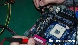
Debugging is a vital part of the process. Start by checking for short circuits using a multimeter. Ensure the power supply is stable and functioning correctly. If the power chip isn’t outputting the expected voltage, check the input, enable signals, and feedback network.
Stable power is the foundation of any circuit. A poor power supply can cause unpredictable behavior. Common power regulation techniques include LDOs and switching power supplies. LDOs offer low noise and fast response but are less efficient, while switching power supplies are more efficient but noisier.
Understanding the working principles of these power supplies helps in making informed design choices. LDOs use a linear approach, adjusting resistance to maintain output voltage. Switching power supplies use a more complex method involving MOSFETs and filtering to achieve higher efficiency.
High-speed signals are often misunderstood. It’s not just about clock frequency but also the rise time of the signal. Fast edges contain high-frequency components, which require careful design to avoid issues like overshoot and ringing.
When choosing an oscilloscope, bandwidth is more important than sampling rate. A rule of thumb is to select an oscilloscope with at least 3x the signal bandwidth. Also, don’t forget to consider the probe’s bandwidth—it can significantly affect your measurements.
Overall, hardware design is a blend of theory, practice, and patience. With time and experience, you'll develop the skills needed to create reliable and efficient circuits.