Utility Pole is a tall structure, usually made of wood, metal, or concrete, that is used to support wires and equipment that deliver electricity to homes and businesses. Electric poles can often be found along the side of the road in residential and commercial areas. Power poles are a vital part of the grid, helping to move electricity from power plants to consumers. Power Pole,Electric Line Transmission Pole,Electric Fencing Pole,Hot Dip Galvanized Pipe JIANGSU HONGGUANG STEEL POLE CO., LTD. , https://www.hgsteelpoles.com
An article tells you what a hardware engineer needs to do.
Time flies, and it's been three years since I first painted my first circuit board. Just like you, I was full of doubts and excitement when I first touched the board. The wealth of information available online about hardware circuits can be overwhelming—terms like signal integrity, EMI, and power supply design might seem intimidating at first. Don’t worry; everything takes time to understand. After reading this article, I believe you’ll gain a clearer understanding of what a hardware engineer does.
Designing hardware circuits involves several key steps. First, you need to define the overall architecture and framework. Some projects may have pre-defined structures, while others require you to create your own. Understanding the reference designs is crucial, as experienced engineers often learn from existing solutions. If no reference design is available, start by selecting the main ICs, checking their datasheets for key parameters, and ensuring they meet your requirements. This process requires patience and continuous learning.
The core of hardware design includes three main parts: schematic design, PCB layout, and BOM (Bill of Materials) creation. Schematic design translates your ideas into a circuit diagram, similar to textbook schematics. PCB layout involves placing components and routing connections based on the netlist generated from the schematic. Finally, the BOM lists all the components needed for the project.
Common tools used in hardware design include Protel (now known as Altium Designer), which is widely used in China due to its user-friendly interface. While more advanced tools like Cadence exist, the fundamental design process remains the same. Whether using Protel or Cadence, the key steps are always: schematic design, PCB layout, and BOM generation.
Now, let’s briefly walk through the design process:

1. **Component Library Creation**: To place a new component on the schematic, you must build a library that defines its pins and properties. This is essential for accurate design.
2. **Schematic Drawing**: Connect components according to the datasheet and system requirements. Understand the difference between wires (which carry electrical signals) and lines (used for annotations).
3. **Netlist Generation**: Convert the schematic into a netlist, which serves as a bridge between the schematic and PCB layout.
4. **ERC (Electrical Rule Check)**: Before moving to PCB layout, perform an ERC to catch basic errors like shorted outputs.
5. **PCB Layout**: Place components and route connections. Pay attention to the board size, layer stack-up, and placement of critical components.
6. **DRC (Design Rule Check)**: Ensure that the layout meets all design rules before finalizing the PCB.
After PCB layout, generate the BOM and prepare for assembly. For small batches, it’s better to assemble the board yourself for easier debugging. Large companies often use specialized software for BOM management.
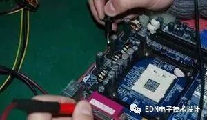
Debugging is a crucial part of the process. Start by checking for short circuits using a multimeter. Then verify the power supply output and stability. Oscilloscopes are invaluable for analyzing power supply noise and signal integrity.
Power supply design is one of the most important aspects of a circuit. A stable power supply ensures the entire system functions properly. There are two main types of power supplies: linear regulators (LDOs) and switching power supplies (PWM). LDOs are simple and provide low noise, but they are inefficient. Switching power supplies are more efficient but can introduce noise and have slower transient responses.
Understanding the working principles of these power supplies helps in choosing the right one for your application. Linear regulators work by adjusting the voltage drop across a transistor, while switching power supplies use a square wave to control the output voltage efficiently.
When dealing with high-speed signals, it's not just about clock frequency—it's about the signal edge rate. Fast edges contain high-frequency components, so proper design is essential to avoid issues like overshoot and ringing.
Choosing the right oscilloscope is also important. While sampling rate matters, bandwidth is even more critical. A good rule of thumb is to choose an oscilloscope with at least 3–5 times the signal bandwidth. Don’t forget to consider the probe’s bandwidth as well.
In summary, hardware design is a complex but rewarding process. It requires a solid foundation, attention to detail, and a willingness to learn. With practice and patience, you’ll become more confident in your ability to design and debug circuits effectively.