Analysis of the ultra-low power integrated mixed signal metering solution based on ADuCM350
The ADuCM350 is an ultra-low-power, integrated mixed-signal metering solution that combines a microcontroller subsystem for processing, control, and connectivity. The core of the system is based on a low-power ARM Cortex-M3 processor, which includes digital peripherals, embedded SRAM, flash memory, and an analog subsystem responsible for clocking, reset, and power management. This highly integrated architecture makes the ADuCM350 ideal for applications requiring precision, low power consumption, and compact design.
This application note provides a detailed guide on how to configure the ADuCM350 to accurately measure the impedance of an RC sensor using a two-wire measurement method. To achieve optimal accuracy, it is crucial to make full use of the 16-bit ADC's dynamic range. This involves calculating key parameters such as the peak-to-peak excitation voltage, the RTIA/CTIA combination, and the value of the calibration resistor. These calculations are essential to ensure that the current flowing into the load remains within acceptable limits, maintaining both performance and safety.
If there are no current constraints, the user can maximize the signal swing at the TIA input to the ADC, which helps improve the signal-to-noise ratio (SNR) and overall measurement quality. However, in applications where the load current is limited—such as in two-wire bioimpedance systems that must comply with the IEC 60601 standard—it becomes necessary to calculate the maximum allowable current and implement appropriate circuit safeguards.
In the example provided in this application note, the goal is to measure the impedance of an RC-type sensor operating at a 1 kHz excitation frequency, using the configuration shown in Figure 1. The sensor’s characteristics are defined by a specific resistance and capacitance setup, which will be analyzed in detail below.
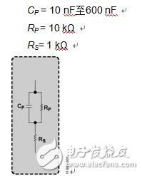
Figure 1. Sensor RC Configuration
The first step in the measurement process is to determine the minimum impedance of the sensor. This allows us to calculate the maximum current that will be fed into the transimpedance amplifier (TIA). In the case of the sensor shown in Figure 1, the lowest impedance occurs when the capacitor CP is set to 600 nF.
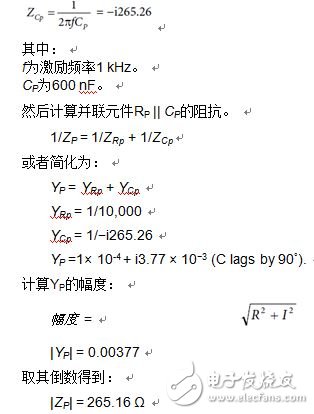
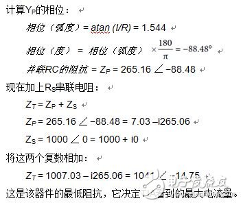
To compute the total impedance ZT, we begin by determining the impedance of the CP capacitor. This is done using the standard formula for capacitive reactance, which depends on the frequency of the excitation signal and the capacitance value.
Three Phase Online UPS,Tower Online UPS,Rack Mount Online UPS,Isolation Transformer
Shenzhen Unitronic Power System Co., Ltd , https://www.unitronicpower.com