Description
-Contact Resistance:≤50mΩ
â—† Small Compact Size, high reliability Rotating Switch,Rotary On Off Switch,Rotary Power Switch,Round Rotary Switch Ningbo Jialin Electronics Co.,Ltd , https://www.donghai-switch.com
-Insulation Resistance:≥100mΩ
-Dielectric Strength:1,500V,
-1min Electronic Life:10,000 cycles
-Operating temperature:T120
-Rating current/voltage:6A 250V AC
Features
â—† Micro contact gap,High speed operation,High sensitirity,Micro operatizon travel.
â—† Long life & high reliability
Traffic Light Control Circuit Design Based on Proteus and Single Chip Computer
Urban roads are complex and interwoven, with traffic lights serving as a crucial command system for managing urban traffic. As an effective method to regulate traffic flow and enhance road capacity, traffic lights play a significant role in reducing traffic accidents. However, traffic volume is constantly changing, while traditional traffic light systems rely on fixed-time control, often leading to congestion. Therefore, designing a simulation and control system for traffic lights using Proteus and a microcontroller holds great practical value in minimizing accidents, easing traffic jams, and improving overall traffic smoothness.
**1. System Design**
At a four-way intersection, the east, west, and north roads meet. Each road has its own set of traffic lights, with each state featuring red, green, and yellow signals. Specifically, every group of traffic lights includes three sets: left-turn, straight, and right-turn. The green light allows passage, the red light prohibits it, and the yellow light serves as a warning that the signal is about to change.
**1.1 Hardware Circuit Design**
When designing a microcontroller-based system, it's essential to keep the hardware as simple as possible while maximizing functionality. This project uses the STC89C52 microcontroller as the central control unit. It communicates with various peripheral modules to manage the entire traffic light system. The system block diagram is shown in Figure 1.
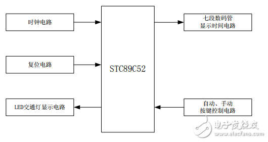
*Figure 1: Block diagram of the traffic light system*
The system comprises a clock circuit, reset circuit, control circuit, LED display for traffic lights, a seven-segment digital tube for time display, and both automatic and manual control buttons. The STC89C52 controls the P1 port for traffic light signals, P0 and P2 ports for time display, and P3 for mode selection. LEDs represent the traffic lights, while the digital tube shows the countdown.
**1.2 Software Circuit Design**
**1) LED Traffic Light Display Module**
The P1 port of the STC89C52 controls the LED traffic lights, switching their states according to the system’s operational mode.
**2) Digital Tube Display Module**
The P0 port handles the countdown, while P2.0 to P2.3 selects the digit for display. A T2 interrupt is used to refresh the seven-segment display every 2 milliseconds.
**3) Keyboard Control Module**
P3.0 to P3.3 and P3.6 are connected to external buttons for manual and automatic control. These allow real-time scanning and switching between different modes.
**2. System Working Modes**
**2.1 Automatic Control Mode**
Initially, the north-south direction has a green light, while others are red. The digital tube counts down from 15 seconds. At 8 seconds, the yellow light starts flashing (once per second). After 3 seconds of flashing, it counts down to 5 seconds. Then, left and right turns become green, while straight is red. When the countdown reaches zero, all green lights turn off, and red lights remain on. The digital tube then counts down from 3 seconds, and the yellow light flashes again. After another 3 seconds, the system switches to the east-west direction with a green light, repeating the cycle.
**2.2 Manual Control Mode**
If the manual button is pressed during automatic mode, the system enters a conduction state, displaying 99 on both digital tubes. If not pressed, the system performs a 3-second yellow flash before entering the selected mode. Pressing other buttons will switch to the corresponding mode. In manual mode, pressing the automatic button returns the system to its initial state. Additionally, crosswalks can be activated based on the current direction, allowing pedestrians to cross safely.
**3. Proteus Simulation Design**
Using Proteus software, the hardware and software designs were simulated together. The program was written in Keil, compiled into a HEX file, and loaded onto the MCU for combined simulation. The results are shown in Figure 2.
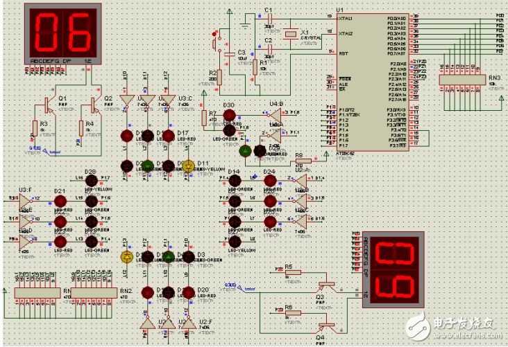
*Figure 2: Simulation results using Proteus and Keil*
This traffic light control system uses the STC89C52 microcontroller, draws the hardware circuit in Proteus, and simulates the program using Keil. It features three traffic lights per road (left, straight, right), operating simultaneously. The system supports both automatic and manual modes. During peak hours or adverse weather, it can be switched to manual control for better traffic management. The system is cost-effective, energy-efficient, and highly scalable, offering broad application potential in smart city development.