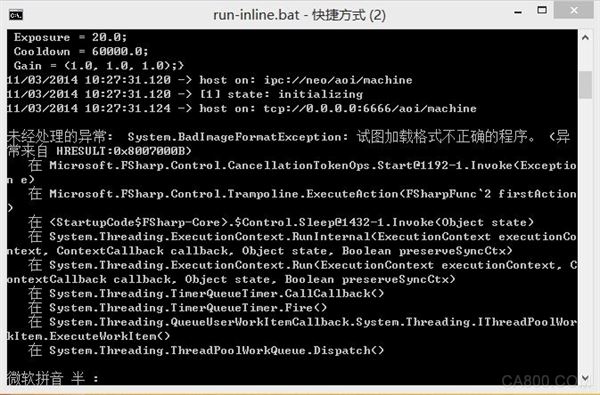
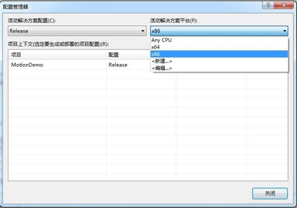
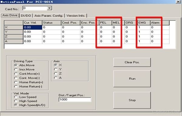
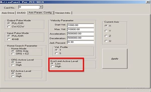
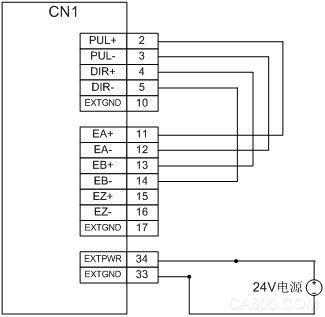
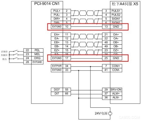
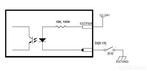
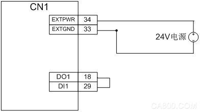
The contents of this manual are written for Solidtech's motion control cards PCI-9014, PCI-9016, and PCI-9074. If the manual contains some errors, please let us know the mistakes we have found and help us improve. We are greatly appreciated. 1 Initialization failed or the test program is abnormally opened After the program is run, the prompt box "XX Initial fail" is displayed, indicating that the card initialization failed. 1.1 Hardware Driver Installation First Determines if Hardware Drivers in Computer Management Are Installed 1. Make sure the card gold finger is clean (clean the gold finger with the eraser) and install the card in the computer slot. 2. Update the card driver. Please refer to the instruction manual for installing the driver. 3, re-plug the card, update the card driver 4, change PCI slot test, change card test, change computer test 5. If you do not recognize the card after completing the above attempt, contact the business and send the card back to the company. 1.2 Administrator privileges If the card number or axis number is very large when the program is started, please consider whether to obtain the administrator rights. When using the win7 and above versions of the system, when directly running the .exe executable program, right-click is required. Programs, and select "Run as administrator", or use other methods to obtain administrator privileges, the results of running the program is normal. 1.3 Program Configuration When using .net for programming, if the setting in the Configuration Manager (under "Generate" menu) is Any CPU, and the program runs with error 0x800700B, the configuration manager settings need to be changed to be consistent with the system configuration. For example, if the computer is a 32-bit system, select "X86" under "Active Solutions Platform" as shown in the figure below. If the computer is a 64-bit system, select "X64" 2 The motor cannot control normally PCI-9014, PCI-9016, PCI-9074 all support multi-threaded function call. If the program written by the customer himself can not be controlled normally, please use the own test program motionpanel to do the test. After confirming that the motionpanel is operating normally, use the example test of the corresponding programming language. Then check your own program. If you do not understand something in the program, you can email some of the test codes directly to the company's email address. We will reply as soon as possible. 2.1 The motor does not move 2.1.1 Open the test software motionpanel, check the limit or alarm, and whether the emergency stop is valid. Limit, alarm display 1 is valid, emergency stop display 0 is valid. If the effective level of the hardware limit is opposite to the default value, please refer to the operation instruction of motionpanel in the user manual to reverse the limit active level. This function is called in the program to invert the level. If the alarm or emergency stop is valid, check the wiring. 2.1.2 Check if the motor has been energized (enable or servo on). Push the shaft with your hand to determine whether the motor has been energized. If not, check whether the Servo On signal of the driver is connected and whether the excitation signal is given. 2.1.3 If the motor has been magnetized, check that the drive control mode is correct. Shengli's motion control card supports the position control mode. Please confirm that the driver's control mode is consistent with the card. 2.1.4 Wiring Incorrect Please refer to the manual driver's wiring in the instruction manual to ensure that there is a 24V external power supply 2.1.5 Insufficient wiring After the power is turned off, check all the sockets and pull it out by hand. It is easy to pull off. Ensure all wiring jacks are connected 2.1.6 If all the above are confirmed to be no problem, and the pulse output mode is direction + pulse, directly use the multimeter's HZ file (measure frequency file), and the two table pens are respectively connected to PUL+ and PUL- so that the control axis can run at speed. In the normal mode, the pulse frequency and the running speed are consistent under normal conditions. Or directly connect the pulse signal terminal to the board pulse feedback signal terminal. That is, PUL+, PUL-, DIR+, DIR- correspond to OA+, OA-, OB+, and OB-, respectively, as shown in the figure below. Then test with motinpanel, pulse output format and pulse input format are set to PUL/DIR format. If the emitted pulse does not coincide with the feedback pulse, it indicates that the board-card pulse has failed. If the test result is normal, it indicates that the card is working properly. Please check other hardware reasons. 2.2 The motor appears jitter or abnormal vibration or the encoder position continues to jump 2.2.1 If it is a control servo, please confirm that the ground of the driver pulse signal or the ground of the pulse feedback signal is connected with the signal ground of the board. Most sports abnormalities are caused by this, so please pay attention. Take Matsushita's server wiring diagram as an example to illustrate: Panasonic drive X5 port pulse signal 13 feet or encoder feedback signal 25 feet one of the signals and board signal ground connectivity 2.2.2 Try to use shielded encoder cable to reduce electromagnetic interference 2.2.3 Use differential wiring as much as possible to avoid electromagnetic interference 2.3 In the premise that the motor only transfers the wire in one direction, the control method of the driver must be consistent with the pulse output mode of the board. The control card has two output modes: PUL/DIR, CW/CCW. Make sure the settings in the drive are the same. 3 Universal input and output are not normal 3.1 The input does not normally provide external 24V voltage. Connect the button to both ends of EICOM and DI (EICOM and 0V are connected in the motion card), open the motionpanel, press the button, observe whether the DI input status changes, or use the external The table voltage file tests whether the voltage values ​​across EICOM and DI change. 3.2 Output is not normal Output is open collector output [1], the output has two states: on and off. The output voltage cannot be measured directly with a multimeter or voltmeter. Unless an external voltage is supplied and the load is connected, high and low levels can be measured. A low level can be measured when the output on the motion card is on. Verify that the load input current size of the device driven by DO is not more than 50 mA per channel. If the drive current is large, increase the driver board (DIN-8D). Excessive current will damage the output chip. When 24V external power supply is already provided and the input is normal and the load current does not exceed the limit, connect the output to the input as shown in the figure below. Then use the motionpanel as a test. If the input display matches the output setting, then the output is normal. If not, it can be determined that the card output input is faulty. [1] Open collector, http://en.wikipedia.org/wiki/Open_collector
To suit the demands of customers as a supplier, wholesaler and trader, we are engaged in offering Battery. Enclosed in polyester tube to stop spillage, these batteries are manufactured with perfection at our vendor's premises. Widely demanded across the nationwide market, these batteries are suitable to use in UPS and inverters.
Led Controller,Led Light Controller,Mppt Solar Charger Controller,Adjustble Controller Delight Eco Energy Supplies Co., Ltd. , https://www.cndelight.com