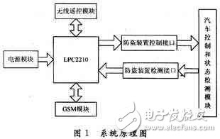
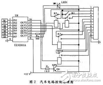
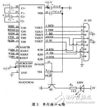
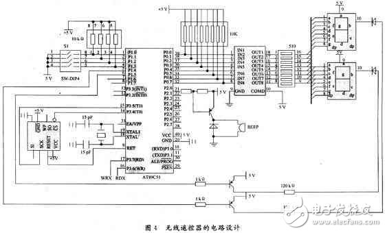
With the rapid development of China's automobile industry, many families own their own private cars, but the number of garages can not meet the demand. Therefore, how to effectively prevent car theft is the most concerned issue for car owners. In recent years, science and technology have developed rapidly, and new types of car anti-theft devices combined with various new technologies have emerged. As the functions of the in-vehicle system are gradually increasing and increasing, the control of the single-chip microcomputer has become increasingly unable to meet the demand. Therefore, the use of embedded technology in automotive electronics will become inevitable. In this paper, the embedded technology is used to develop the vehicle anti-theft device, which can enhance the control ability and improve the intelligence of the car anti-theft. On the other hand, the size of the device is reduced, the flexibility of the application of the device is increased, and an extended space is provided for further enhancing the function of the automobile electronics in the future. Due to limited space, this article only introduces the hardware circuit. 1 system hardware components The system is mainly composed of ARM embedded controller, mobile phone module, wireless remote control module, car control and status detection module. The vehicle control and status detection module collects the vehicle related data to the ARM embedded controller, and the ARM embedded controller transmits it to the mobile phone module and the wireless remote control module to finally achieve the purpose of the alarm. The system principle is shown in Figure 1. 1.1 Control circuit If a car thief vibrates after starting the car abnormally, the vibration sensor will send the low-level effective signal to the LPC2210, and the LPC2210 will transmit the information; one is transmitted to the alarm circuit and the other is transmitted to the TC35. The alarm circuit is mainly composed of an integrated block, a speaker and an electronic switch SCR. The triode or composite tube is a circuit measure commonly used to improve power. It constitutes an equivalent transistor with a large current amplification factor, and the total amplification factor is the product of the amplification factors of the two tubes. SCR is an electronic switch composed of thyristor. The capacitor and resistor form a buck and filter, which provides +3~+4 V voltage to the IC. The IC is a simulation sound alarm integrated circuit. The alarm is controlled by SCR. Once the car thief presses the wrong password, the battery current is divided into the anti-theft system, and the other is after the engine is started, after the engine is started, the output voltage of the neutral contact is passed through the differential circuit, and the thyristor SCR is triggered. The resistor is stepped down, and the voltage is applied to the power input end of the IC. The IC obtains a voltage output alarm signal, which is amplified by the composite tube to illuminate the speaker to emit a loud alarm sound. In the static state, the entire circuit does not consume power. as shown in picture 2. 1.2 Power Interface Design The GSM module works with a voltage of 3.3 to 5 V. In the process of starting the connection transmission to the network, the power supply is required to provide a peak current of 2 A, and the voltage drop of the voltage cannot be greater than 400 mV. Therefore, the module power supply design must be sufficient. Consider that the voltage may drop. It must be ensured that the minimum voltage is higher than 3 V. In addition, during data transmission, the voltage fluctuation cannot be greater than 400 mV. Otherwise, the TC35 will consider the voltage to be too low and automatically shut down the module. Therefore, the power cord of the circuit should be as short as possible. If you use the battery clip as a backup power source, consider the voltage drop caused by the resistance on the motherboard and battery clip wires. In the circuit design, the power supply of the ZIF interface can be separately powered from the other power sources. The ZIF interface power supply is separately powered, and the above requirements must be ensured. The high-power device can be powered by a high-stability switching power supply. 1.3 Serial Interface Design The GSM module and system processor exchange data over the serial TIU TRS 232 standard serial bus. The high level of all operations is CMOS voltage (2.65 V). Therefore, the logic level of the RS 232 conversion chip must be in the form of low voltage supply (3.3 V), and the serial conversion chip of 5 V cannot be used. In the design, MAX's MAX 3238 was selected for data conversion. The MAX 3238 is a 3.3 V logic-level serial-to-conversion chip from MAX that has the same characteristics as the popular MAX 232 except that the logic level is 3.3 V. Serial communication between the module and the processor is fully compliant with the Universal Serial Bus standard. The specific hardware interface circuit is shown in Figure 3. 1.4 S1M card interface design The baseband processor in the GSM module has a complete SIM card interface that is fully compliant with the ISO7816 3 standard. To ensure greater stability during SIM card interface design, the maximum length of the ZIF connector and the card pins should not exceed 200 mm. One issue that needs to be considered during design is the ground handling of the SIM card. Of course, there are many different ways to follow your own design habits and styles. The ultimate goal to be achieved is to have a SIM card holder with a separate ground. Therefore, a set of filter circuits is formed by one inductor and one capacitor, and a set of one side is placed on each side of the card holder to form an annular spacer, so that the SIM card and the outside maintain a relatively independent ground, and then pass through a The line connects the module interface ground to the ground of the SIM card. 1.5 Wireless remote control module design The wireless remote control function is implemented by the SRWF-1 module, and is controlled by the 89C51. The information received by the C51 is sent to the SRWF-1 transmitting module through the serial port, and the SRWF-1 receiving module transmits the received information to the LPC2210 through the serial port. 2 Conclusion It has been verified by experiments that the use of GSM short message-based communication method to control the car alarm system can not only greatly improve the communication reliability of the alarm system, but also the communication distance is basically unlimited, thus realizing the user's long-distance real-time monitoring of the car; It is also possible to distinguish the urgency of the invasion, so that the user can take measures according to the situation to meet the requirements of the automobile user for the automobile anti-theft, and the system is not costly and easy to promote. Metal USB memory sticks is stand out from common USB drives and have
more than 70 styles metal USB Flash drives for your choose .such as Gold
bar USB drives,USB Key shape series and Metal Racing card .. All of
them can do laser engraved LOGO or silkscreen. It looks amazing with
laser engraved LOGO or any message that you want to show. Metal USB
memory sticks also classify many different materials , zinc
Alloy,stainless steel and aluminum . They have different advantage. The
Aluminum USB drives can do kinds of different colors .Metal USB is on
behalf of high quality company gifts to market your brand ,contact with
us for more information about metal USB series . Metal USB Flash Drive,Micro USB Flash Drive,Metal USB Stick,Metal Flash Drive Custom Usb Gift company limited , https://www.customusbgift.com