Using the principle of capacitor charging and discharging to realize one IO realizes two buttons
A few years ago, I visited a friend and mentioned that the cost of customer products has become very high, especially in the toy industry, where even the smallest details are calculated down to the cent. My friend was surprised and said that in order to cut costs, solution providers are constantly brainstorming different implementation methods. He was amazed that someone would try to use a single microcontroller IO pin to simulate the function of two buttons, which sounded really novel to him. I had never thought about it before, but since others could do it, I felt I should be able to figure it out too. It was time to find a way to make it work.
I have a habit. When I come across a problem, I usually try to solve it before going to bed. If I can't find the answer, I might not sleep well. But if I think about it enough, sometimes I fall asleep anyway. I knew how to use a single IO pin to detect multiple buttons, and most of the time this is done using ADC (Analog-to-Digital Converter) functionality. By using a resistor divider, you can measure the voltage level and determine which button is pressed. However, if the IO doesn’t support ADC, there’s still a way—by using capacitor charging and discharging techniques. This allows for indirect measurement through standard IO pins, as described in my previous article on keyboard scanning. So, I decided to try using this principle with two buttons and found a working method.
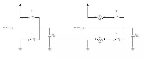
Let’s take a look at the left part of the diagram. Suppose MCU_IO1 is a bidirectional IO port, and the program follows these steps:
- Set MCU_IO1 as an output and drive it high for a certain period. During this time, the capacitor C1 charges up to near the supply voltage.
- Change MCU_IO1 to input mode. If neither J1 nor J2 is pressed, the IO will act like a high-impedance resistor. The charge on C1 will slowly discharge through this resistance, causing the voltage on C1 to drop over time. If we read the status immediately after switching to input, we’ll see a high value (1).
- Set MCU_IO1 back to output and drive it low. Regardless of the current state of C1, after a while, the capacitor will be discharged to near zero volts.
- Switch MCU_IO1 back to input mode. If neither J1 nor J2 is pressed, we’ll read a low value (0). However, if J1 is pressed, the capacitor is connected directly to the power supply, so during step 2, the reading remains high (1), but during step 4, it becomes high again. Similarly, if J2 is pressed, the capacitor is connected to ground, and during step 2, the reading drops to low (0), but during step 4, it remains high (1). This difference in readings allows us to determine whether J1 or J2 is pressed.
Now that I’ve found a way, I need to test its reliability. What if J1 is pressed while the IO is set to low? That could short the power supply to ground, potentially damaging the MCU. The same issue happens when J2 is pressed and the IO is set to high. Worse yet, if both J1 and J2 are pressed simultaneously, the power supply and ground are directly connected, creating a short circuit that could destroy the entire system.
But don’t worry. Looking at the right side of the diagram, there are 220-ohm resistors connected to each switch (J3 and J4). This prevents any direct short-circuit, no matter how the switches are pressed. Using the same four-step process, we can determine whether J3 or J4 is pressed. However, if both are pressed at the same time, the system may not be able to distinguish between them. Still, this approach is much safer and effective for most applications.
High-frequency Transformer,Switching Power Supply Transformer,Ring Electronic Transformer,High Frequency Electrical Transformer
Xuzhou Jiuli Electronics Co., Ltd , https://www.xzjiulielectronic.com