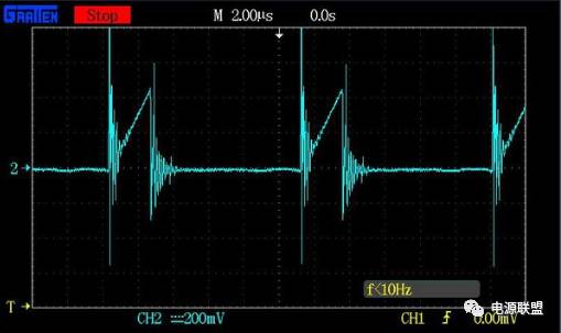
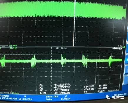
1. Low-frequency ripple is primarily associated with the capacitance of the output filter capacitor in the power supply circuit. Although increasing the capacitor size can reduce ripple, there are practical limitations due to physical and cost constraints. As a result, some low-frequency ripple remains. After being filtered by the DC/DC converter, this AC ripple appears as low-frequency noise at the output. The level of this noise depends on the ratio of the DC/DC converter and the gain of the control system. Current-mode control DC/DC converters generally offer slightly better ripple rejection compared to voltage-mode ones, but low-frequency AC ripple is still significant. To achieve a low-ripple output, it's essential to apply additional filtering. This can be done through pre-regulation stages or by increasing the closed-loop gain of the DC/DC converter. Common methods for suppressing low-frequency ripple include: a. Increasing the inductance and capacitance values in the output low-frequency filter to bring the ripple within acceptable limits. b. Implementing feedforward control techniques to reduce the low-frequency ripple component before it affects the output. 2. High-frequency ripple noise originates from the high-frequency switching components in the power supply. When the DC input is switched at high frequency, the rectifier and filter circuits shape the output. The high-frequency ripple at the output is influenced by the switching frequency of the power supply and the design of the output filter. To minimize this noise, it's beneficial to increase the operating frequency of the power converter, which allows for smaller and more effective filtering components. The main goal of high-frequency ripple suppression is to provide a clear path for high-frequency noise to be filtered out. Common strategies include: a. Raising the operating frequency of the power supply to shift the ripple to higher frequencies, making it easier to filter. b. Enhancing the output high-frequency filter to suppress unwanted high-frequency components. c. Using multi-stage filtering to further reduce the ripple noise. 3. Due to parasitic capacitances between the power device and the heat sink, as well as between the primary and secondary sides of the transformer, and due to parasitic inductance in the wiring, common-mode ripple noise can appear at the output when a rectangular wave voltage is applied. To mitigate this, it's important to reduce these parasitic capacitances and add common-mode inductors and capacitors on the output side to suppress the noise. Common methods for reducing common-mode ripple noise include: a. Using a specially designed EMI filter on the output to block common-mode noise. b. Reducing the amplitude of switching glitches that contribute to noise generation. 4. Ultra-high frequency (UHF) resonant noise is mainly caused by the reverse recovery of high-frequency rectifier diodes, as well as the resonance between the junction capacitance of the power device and the parasitic inductance in the wiring. This type of noise typically occurs in the range of 1–10 MHz. Selecting diodes with soft recovery characteristics, minimizing junction capacitance, and reducing the length of wiring can help suppress UHF noise. Switching power supplies often use closed-loop control to regulate the output voltage. However, if the regulator parameters are not properly designed, this can lead to ripple. Fluctuations in the output may enter the feedback network, potentially causing self-oscillation and adding extra ripple. This kind of ripple usually doesn’t have a fixed frequency. In many cases, output ripple in switching power supplies is caused by improper selection of regulator parameters. To address this, the following measures can be taken: a. Adding a compensation network to the ground to suppress ripple caused by self-excitation in the regulator. b. Choosing an appropriate open-loop gain and other parameters for the closed-loop regulator. If the gain is too high, it can cause oscillation or instability, increasing ripple. Conversely, if the gain is too low, the output voltage stability may be compromised, also leading to higher ripple. Therefore, the regulator’s parameters must be carefully selected and adjusted based on load conditions during testing. c. Avoiding the inclusion of pure delay elements in the feedback path. Minimizing delays improves the speed and responsiveness of the closed-loop regulation, helping to reduce output voltage ripple.
The control switch is a special switch for process control of electrical control and thermal instrumentation. Specifically, there are positioning operation, self-resetting operation, positioning-self-resetting operation, blocking operation, positioning-blocking operation, self-resetting-positioning-locking operation and so on.
The types of control switches are:
ME Limit Switch Control Switches,Float Switch,Proximity Switch,Cam Switch Ningbo Bond Industrial Electric Co., Ltd. , https://www.bondelectro.com

Micro Switch
QS5 Cam Switch
Universal Changeover Switch
Foot Switch
Proximity Switch (Sensors)
Switching Power Supply Unit
Float Switch
Weather Proof Isolating Switch
Isolating Switch and Changeover Switch