Solar Energy Mounting Ground Screw Pile
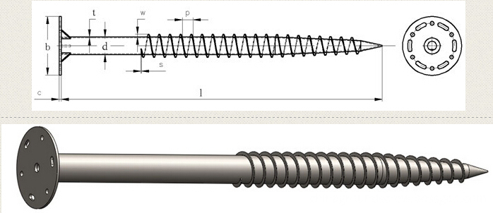
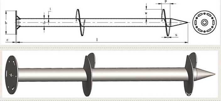
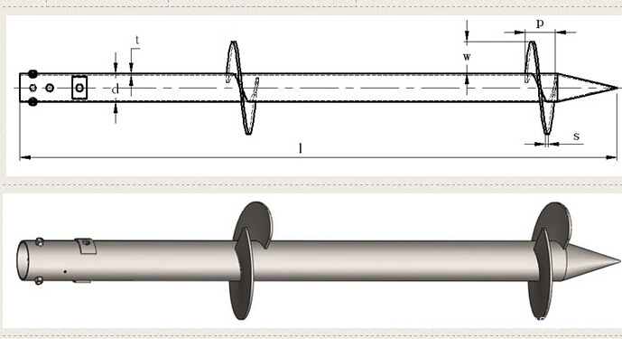
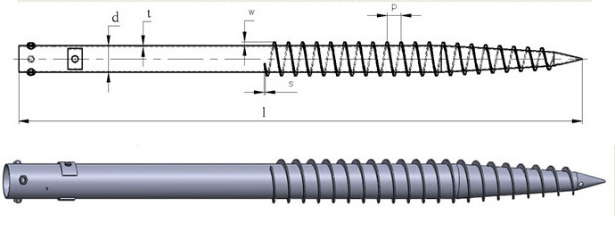
Solar Energy Mounting Ground Screw Pile with N series and F series mainly .N Series Ground Screw with 3pcs,4pcs or 6pcs nut and reinforced plate to assemble ,F Series Ground Screw with flange to assemble solar brackets .
There are two kinds of N series Ground Screw mainly ,with 1 or 2 or 3pcs big blade ,and with Nuts and reinforced plates,another kind of ground screw with continuous small blades .F series ground screw with round,hexagon ,triangle or square flanges .with big blade or continuous blade .
Ground Screw Pile for solar energy mounting system with many advantage : no-digging,no waste time ,lower cost,protect environment,easy install . Solar Energy Mounting Ground Screw System,Ground Screw Pile Foundation for Solar,10Kw PV Panel Mounting System,Ground Screw Solar Rack System BAODING JIMAOTONG IMPORT AND EXPORT CO., LTD , https://www.chinagroundscrew.com


Look at how senior engineers design RF boards, and these ideas are earned.
RF board design has long been one of the most challenging aspects for engineers, often seen as a nightmare due to issues like electromagnetic interference (EMI). To achieve a successful design on the first try, careful planning and attention to detail are essential before starting the actual work. This article explores key considerations in RF board design, focusing on partitioning techniques, microvia types, shielding, power supply decoupling, and more.
RF board design is frequently referred to as a "black art" due to its many theoretical uncertainties. However, this is only part of the story—there are still clear rules and guidelines that can be followed. The real challenge lies in knowing how to compromise these rules when constraints make full implementation impossible. Key topics include impedance matching, material selection, wavelength management, and harmonic control. This article will focus on the critical aspect of RF board partitioning.
**Types of Microvias**
Circuits with different functions must be separated but still connected without causing electromagnetic interference. This is where microvias come into play. Typically ranging from 0.05 mm to 0.20 mm in diameter, microvias are categorized into three types: blind vias, buried vias, and through vias. Blind vias connect surface layers to inner layers but do not go all the way through the board. Buried vias are entirely within the inner layers and are used for internal connections. Through vias, on the other hand, extend through the entire board and are often used for interconnections or as positioning holes during assembly.
**Partitioning Techniques**
When designing an RF board, it’s crucial to isolate high-power RF amplifiers (HPAs) and low-noise amplifiers (LNAs) as much as possible. In simple cases, keeping the RF transmission path away from the receiving circuit works well. However, when space is limited, components can be placed on opposite sides of the board or designed to operate alternately rather than simultaneously. High-power circuits may also include RF buffers and voltage-controlled oscillators (VCOs).
Partitioning can be physical or electrical. Physical partitioning involves component placement, orientation, and shielding, while electrical partitioning includes power distribution, RF trace routing, and isolation of sensitive signals.
**Physical Partitioning**
Component layout is central to achieving a good RF design. A key technique is to place components along the RF path and adjust their orientation to minimize signal path length. Keep the RF input away from the output and ensure that high- and low-power circuits are well separated. For mobile phone PCBs, the low-noise amplifier is often placed on one side, and the high-power amplifier on the other, connected via a duplexer. Careful use of blind vias helps prevent RF energy from leaking between layers.
**Metal Shields**
While physical separation is ideal, sometimes metal shields are necessary. They help contain RF energy but come with trade-offs such as increased manufacturing costs and complexity. Properly designed shields should have grounded areas around them, and signal lines entering the shield should be routed internally to avoid interference.
**Power Supply Decoupling Circuits**
Proper decoupling is vital for RF chips, which are highly sensitive to power supply noise. Each chip may require multiple capacitors and an inductor to filter out noise. The placement of these components is critical—capacitors should be as close as possible to the IC pins, and inductors should be placed near the capacitors to minimize coupling.
**Electrical Partitioning**
Modern devices often run on multiple power supplies, creating additional isolation challenges. Power lines should be decoupled early, and high-power traces should be wide to reduce voltage drop. Grounding must be carefully managed to avoid unintended coupling channels.
**RF Output and Input Separation**
Keeping the RF output away from the input is crucial to prevent feedback and instability. Filters should be surrounded by ground planes, and signal lines should be kept away from filter pins to maintain performance.
**Buffers and VCOs**
Buffers improve isolation by splitting signals and driving different circuits. Voltage-controlled oscillators (VCOs) convert voltage to frequency but are sensitive to noise. Their control lines require careful handling to avoid introducing unwanted frequency variations.
**Resonant Circuits**
Resonant circuits are used in transmitters and receivers, working closely with VCOs. They require precise placement of inductors and capacitors to maintain stability and performance.
**Automatic Gain Control Amplifiers**
AGC amplifiers manage signal strength but can introduce noise if not properly designed. Short signal paths and good grounding are essential to minimize interference.
**Grounding**
A solid ground plane is crucial for RF performance. Digital and analog circuits should be separated, and all RF components should be grounded effectively. Using microvias can help manage complex RF layouts without increasing costs.
In conclusion, while RF design may seem like a "black art," following established rules and learning from best practices can greatly improve success rates. Attention to every detail, from component placement to grounding, is essential. This level of precision is often overlooked in many electronics cultures, but it's what separates a functional RF board from a reliable one.