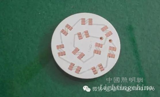
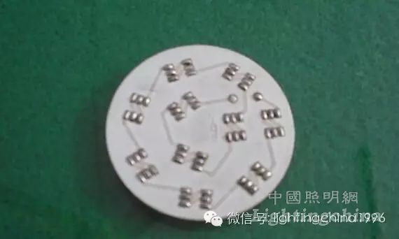
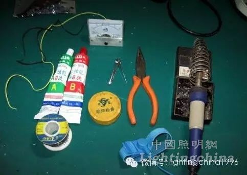
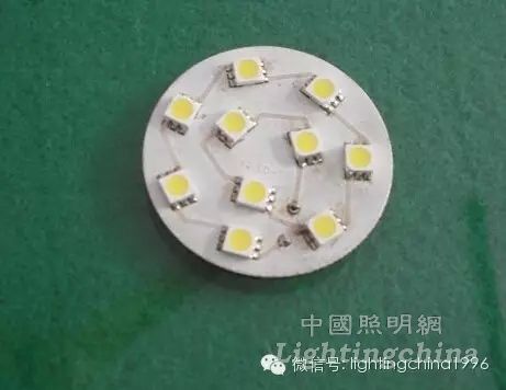
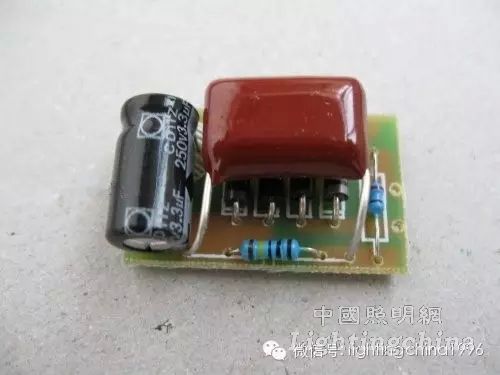
The production process of a SMD LED energy-saving lamp and the simple production process of the SMD LED lamp include a circuit diagram of the SMD LED energy-saving lamp. The following is a circuit diagram of the 10 SMD LED lamp: Figure 1 is a practical circuit diagram of a patch LED lighting fixture. The lamp is powered by a 220V power supply. The 220V AC is stepped down by a C1 step-down capacitor and then rectified by a full bridge and then filtered by C2. The current limiting resistor R3 is connected to 10 in series. The SMD LED provides a constant current power supply. The rated current of the SMD LED is 20mA, but we must consider the influence of many factors on the SMD LED when making the energy-saving lamp, including the problem of light decay and heat, the temperature of the LED. Light decay and life have a great influence. If the heat is not good, it is easy to produce light decay. Because the characteristic of LED is that the temperature will increase, the current will increase. Therefore, the problem of heat dissipation during high-power illumination is the most important and will affect. To the stability of the LED, the low power generally adopts the self-heating method, so the current should not be too large in the circuit design. In the figure, R1 is the protection resistor, R2 is the discharge resistor of the capacitor C1, and R3 is the current limiting resistor to prevent the voltage from rising. And the temperature rises the LED current increases, C2 is the filter capacitor, the actual filter circuit can be used in the LED circuit, C2 is used to prevent the impact current on the LED when the light is turned on, the moment of turning on the light because of the existence of C1 Have a big charging current, the electricity Flow through the LED will damage the LED. With the intervention of C2, the charging current of the light-on is completely absorbed by the C2 to protect the light. The circuit is the most practical circuit for the small-power lamp cup. Conveniently installed in a small cup of light, it is now widely used in lamp cups. Advantages: constant current source, low power consumption, small size, economical and practical. But in design, the step-down capacitor should be pressure-resistant. For polyester capacitors or CBB capacitors above 400V, the filter capacitors must have a withstand voltage of 250v or more. This circuit is suitable for driving 7-12 20mA SMD LEDs. Figure 2 is a circuit board diagram PCB figure 2 This round plate is more troublesome to hand-made, it is recommended to buy a finished board. Here is a brief introduction to the whole process of production. image 3 Put the tin on the lamp board, be sure to be uniform, tin should not be too thin or too thick. Production tools: (see Figure 4) 1 needle-nosed pliers or diagonal pliers, thermostat electric iron with grounding wire, anti-static bracelet, nail scissors, high quality fine solder wire, high quality rosin, AB glue, preferably a DC ammeter 50mA (can not be replaced by a multimeter) ). Select patch LED SMD LED should use high brightness, product brightness: 5500-6000MCD (pure white light), voltage: 3.2-3.4V, current: 20MA, soldering temperature: 250 illumination angle: 120 color temperature: 5500K. Install the solder patch LED: Install the board face up, and put the polarity of the chip LED in the direction. Note that there is a corner on the front of the chip LED. The foot is positive (6 feet in total). The installation direction should be the same. Because the patch LED is unidirectionally conductive, this circuit uses a series circuit, as long as one of the counter-group lights does not illuminate. 6 feet are good for the tin that has just been applied. After fixing the patch LED by hand, it can be welded. The soldering should use 30-35W soldering iron and grounding wire. The soldering temperature should be controlled within 240 degrees, and the time should not exceed 2 seconds. This way the light board is assembled. (Figure 5) Figure 5 The next step is to assemble the power supply. The welding of the power supply is simpler. The welding is successful as shown in the figure below. Because there is limited space in the lamp cup, the components need to be sorted to reduce the volume and facilitate installation. (Figure 6)