Regarding "the most suitable capacitor and inductor for switching power supply", I have talked a lot about capacitors before. Please talk about inductance. I think that inductor is one of the important components for building a switching power supply. However, it has been difficult to understand magnetic components including inductors. Indeed, there are not many people who are not good at magnetic components. Despite this, until now switching power supplies are a must-have item and cannot be avoided. Next, in order to deepen our understanding of the inductance, I will answer some questions. So, what is the entry point that should be mastered? The nominal inductance value is of course a mandatory item. The measurement frequency is 100 kHz as shown in the last column and the tolerance is ±30%. The DC superimposed current is taken as an example for description. The idea of ​​temperature rise allowable current is also the same. The DC superimposed allowable current in this example is specified as a current when the DC current is increased and the inductance value is -30%, that is, 30%. Not only is it limited to inductance, there must be fluctuations in values ​​between individual products. The typ value is one of the representative values. The guaranteed value is a value that specifies the maximum and/or minimum allowed. Therefore, it is a value that has a margin for the typ value. For the actual measurement, the multi-value is close to the typ value, but it also includes individuals close to the maximum and minimum values. This is a characteristic of an inductor, and the material and structure of the inductor are different, and these parasitic components also change. Car Connector,Smt Patch Car Connector,Waterproof Patch Car Connector,Automotive Car Connector Shenzhen Jinyicheng Electronci Technology Co.,Ltd. , https://www.jycconnector.com
First of all, I would like to introduce the reading of the inductance specifications, although this is a very basic knowledge. The first thing I want to say is that even if it is the same specification project, the conditions for the project are different depending on the product and the manufacturer. This is very common. Similarly, for a project of the same specification, for example, a manufacturer guarantees a maximum (Max.) and a minimum (Min.), while another manufacturer only proposes a Typical value (typ/representative/standard value), similar to this type. The situation is mixed. Therefore, attention should be paid to the selection of inductors and comparison with similar products.
- In other words, do you need to carefully confirm the required conditions?
indeed so. Don't forget this, if you only compare the values ​​provided, it can sometimes have serious consequences. Next, let's take a look at it. The following table is an excerpt from our product catalog. 
The self-resonant frequency is the limit frequency at which the inductor operates. The minimum is guaranteed here. Indicates normal operation within a frequency range that does not exceed the stated minimum.
The DC resistance is the resistance of the winding resistance, which is marked as a condition with a tolerance of ±20%.
The rated current is one of the items that require careful confirmation of the conditions. One of them specifies the DC superimposed allowable current. In the case of this inductance, it represents the maximum value of the current value of the DC superimposed inductance value of -30%. Different manufacturers/products have different conditions (-10% to -30%).
As another rated current, a temperature rise allowable current is specified. The maximum value of the current value at which the temperature rises by 40 ° C when the DC current is applied is specified, and the condition varies depending on the manufacturer/product (20 ° C to 40 ° C).
There is one more point to note about the rated current. Not every manufacturer/each product provides both DC superimposed allowable current and temperature rise allowable current. In general, when only one of them is provided, it can be considered that the smaller one is specified from the rated angle, and it is better to confirm it to the manufacturer for the sake of insurance.
Since the rated current is an important item, I will explain it in more detail. The figure below is a graph showing the relationship between DC superimposition and temperature rise characteristics and maximum value, typ value, and margin. 
Confirm typ and maximum/minimum to see how much margin there is. In addition, comparing the characteristics with the specified conditions, it can be seen that the provisions under loose conditions or under strict conditions.
- By the way, why are the conditions for the same feature different between products or manufacturers?
The reason can not be generalized. I think it is mainly for the performance requirements and safety of the application circuit. What conditions are most suitable, and the considerations of different manufacturers are different. Of course, it also involves conditions such as product performance, characteristics, quality, reliability level positioning, and price.
- What else needs to be confirmed as an entry point? 
In addition to understanding the specifications, in order to understand the basic characteristics of the inductor, you need to know the equivalent circuit and components. When talking about capacitors, parasitic components such as ESR and ESL and their effects are introduced, and the inductance also has parasitic components.
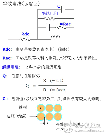
Use the equivalent circuit for explanation. Rdc is mainly the DC resistance of the coiled wire, also known as "copper loss". This is the component in series with the inductor. Rac is mainly the loss of core material, also known as "iron loss." As indicated by the capacitance and resistance, it has frequency characteristics. When the frequency is high, the impedance decreases and the loss increases. The insulation resistance is a DC resistance corresponding to the leakage current. Since the capacitor is insulated by a film such as urethane, the winding is produced by the same structure as the conductor sandwiching the insulator, that is, the capacitor. This line capacitance is the main capacitance and has a large effect on the resonance point.
Q is an indicator of the performance of the inductor. Dividing the value of X(= ωL) by R(Rac) indicates how much loss is there for the frequency. It can be seen from the formula that when R (Rac/iron loss) is small, Q becomes large.
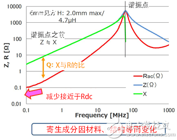
The basic characteristics of the inductor are represented by a graph of frequency and resistance/impedance. This is an example of a 4.7?F inductor with a 6 mm square and a height of 2 mm. The red line is Rac/iron loss. The blue line is the impedance and the green line is X(ωL).
As mentioned earlier, there is a resonance point due to its capacitance. The frequency of the green line X after the resonance point indicates the characteristics of the capacitor body, and the higher the frequency, the lower the impedance. Rac increases as the frequency increases. Rdc is Rac at DC (zero Hz). 