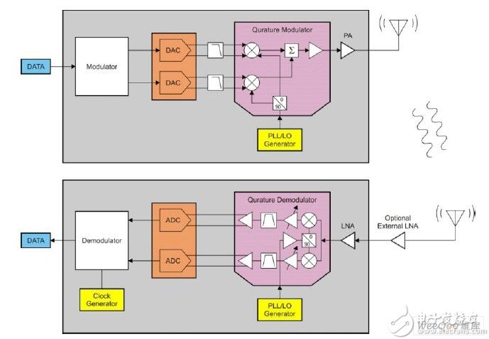
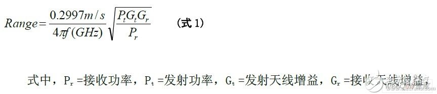
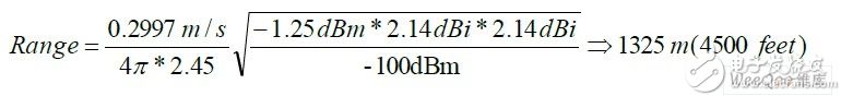
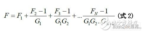
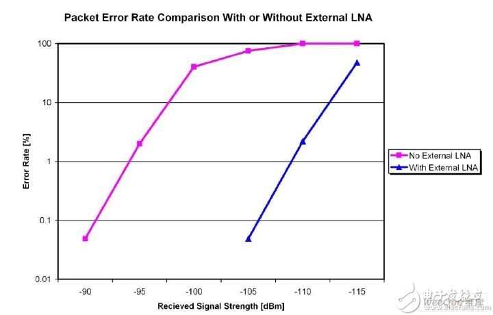
In this paper, we will discuss some methods for optimizing the transmission distance of low-power wireless systems, subject to the FCC's provisions for open single-channel radios in the open ISM band (915MHz or 2.4GHz). The FCC stipulates that for these devices, the fundamental output power should not exceed -1.25dBm. If additional link margins are required, the FCC specification requirements are briefly described. Typical low power wireless link A typical low power wireless link consists of a transmitting device and one or more receiving devices. The transmitting device consists of a modulator, synthesizer, upconverting mixer and a power amplifier (PA). The receiver consists of a reciprocal device, a low noise amplifier (LNA), a downconverter, a synthesizer, and a demodulator. Figure 1: Block diagram of a typical low-power wireless transmitter (top) and receiver (bottom). This is a compromise between performance and power consumption for low-power wireless devices. External amplifiers (whether external LNAs or external PAs) are added to systems that require long-distance communication to increase link margin. Figure 1 shows how to add an external LNA at the receiving end to optimize the wireless link margin. This complies with the FCC regulations and increases the link margin without increasing the complexity of the transmitter. Theoretical communication distance of low-power wireless links The theoretical limit of the wireless link communication distance is determined by the Friis equation (see Equation 1): Communication distance = antenna distance (m). The Fries equation defines the theoretical limits of a wireless link. However, in all real-world systems, the actual link does not. For example, if the Fries equation is used to calculate the maximum communication distance of a 2.45 GHz wireless link, the transmit power is -1.25 dBm, the receive sensitivity is -100 dBm, and the gain of both antennas is 2.14 dBi. It should be noted that 2.14dBi is the theoretical gain of the dipole antenna, which is generally not taken into account when considering losses. However, if you want to achieve these results in a real-world environment, you will quickly discover that this is impractical. The main reason is that the assumption of free space radiation does not apply to terrestrial systems. For some visual distance applications, wireless link applications with 100-200 meters distances work better, while 50-100 meters distances in typical multi-path environments work better. To increase the communication distance of the system, you can choose one or more of the following methods. Each method has a system gain, but at the expense of power consumption or total system cost. First, you need to consider the operating frequency and antenna. Neither generates current consumption, so it should be evaluated before adding an external power amplifier and/or low noise amplifier. 1. The communication distance is related to the square root of the RX and TX antenna gains, and as the antenna specifications increase, the size and price increase. 2. There is a linear relationship between the working frequency and the communication distance. The lower the operating frequency, the farther the communication distance is. However, the available bandwidth decreases as the frequency decreases, resulting in a lower data transfer rate. The following two methods can also increase the system communication distance, but also increase power consumption and total system cost. 1. Increasing the output power of the transmitter (Pt) can increase the communication distance. The communication distance is related to the square root of the output power. For example, the CC2590 provides 14dBm of power with a current consumption of 25mA, which provides 15.25dB improvement for the system. The CC2591 provides 22dBm, which can bring 23.25dB improvement to the system, but the current consumption is up to 112mA. 2. The communication distance is also related to the square root of the input sensitivity (Pr), so the input sensitivity can be increased to increase the communication distance. A typical external LNA consumes approximately 2-4 mA of current. Therefore, if satisfactory performance is obtained, this method has certain advantages over the external PA without considering the FCC/ETSI regulations. For systems with transmit power requirements exceeding -1.25dBm, the FCC requires a frequency hopping scheme to meet the specifications [1]. This solution is processor intensive and challenging to implement. Therefore, for a true low-power wireless system, it may be better to use other methods to increase the communication distance. In order to estimate the possibility of improving the receiving sensitivity, we used the CC1101 (a low-power wireless transceiver operating at 915MHz) for experiments. We chose this device because it works below the two bands we discuss here. Method for optimizing receiving sensitivity The receiver's receive sensitivity value is affected by many components in the receiver chain. See the typical architecture of the low-power wireless receiver shown in Figure 1. If you ignore the cable and matching losses, there are only four subsystems left in the receiver: the internal LNA, the down-converter, the analog-to-digital converter (ADC), and the detector. Where F = total system noise figure, Fn = noise figure for each subsystem, Gn = gain (loss) for each subsystem. Given the noise number (Fn) and gain (Gn) for each subsystem, Equation 2 represents the cascaded noise figure of the receiver stage. Note that the noise figure of the first subsystem is the main component of the total noise figure. If the first subsystem behaves as a high gain, the noise figure of the rest of the system becomes meaningless. This is because the noise figure of each subsequent system is divisible by the gain of the previous subsystem. By measuring the bit error rate (BER) performance at a given bit rate for a system, after the receiver (RX) filter bandwidth is known, the system noise figure can be solved. The results of the CC1101 and CC2500 transceivers are approximately 18 dB. It is not the best result compared to the advanced external LNA [3], but it is more competitive than some other low-power wireless transceivers. In this experiment, we used the Infineon BGB707L7 LNA to add to the CC1101 radio with a working frequency of 915MHz. The CC1101 radio is configured for a low data rate of 38.4 kbps using 9.6 kHz frequency offset FSK modulation. The external LNA has a noise figure of less than 1dB and a gain of 20dB while consuming a current of 2.5mA [3]. The combination of very low noise figure and high gain is ideal for such applications where high receiver sensitivity is sought. Figure 2 shows an improvement in reception sensitivity of nearly 15 dB, which was obtained when the Infineon BGB707L7 LNA was used in front of the CC1101 transceiver. These results can be ported to many TI devices, including the CC2500 and other TI low-power RF SoC devices (eg CC2430 and CC2530). Figure 2: Comparison of packet error rates for low-power wireless receivers with/without external LNA. In this example, a gain improvement of 15 dB is achieved. In this example, the same link margin gain, or 15 dB, is obtained by adding an external LNA or adding an external PA using CC2590. Therefore, it is easier to compare performance and power consumption. It is worth mentioning that the CC2590 consumes 25mA to increase the link margin of 15dB, while the LNA consumes only 2.5mA. Therefore, it is beneficial to add a good performing LNA to the system before adding more output power. Summary of this article According to this experiment, adding a low noise amplifier helps to optimize the receiver sensitivity before increasing the output power, because 1) it has lower power consumption when increasing the same communication distance; 2) because it is not needed Any frequency hopping scheme [1], which reduces the complexity of the transmitter. In a subsequent article, I will discuss the effects of multipath fading and some common methods of obtaining reliable wireless links in these environments. Mineral Insulated Cable,Copper Mineral Insulation Cable,Copper Core Copper Sheath Cable,Fire Resistant Cable Baosheng Science&Technology Innovation Co.,Ltd , https://www.bscables.com