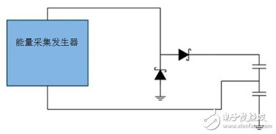
In order to fully realize the potential of Industry 4.0, factories and equipment need to install sensors. With so many sensors, wired installations are disabled, so wireless technologies such as wireless HART and the upcoming Bluetooth® low-energy network are a direct consideration. However, the cost of battery replacement for these sensors is often underestimated. Without the use of a battery, the sensor-driven sensor being monitored by the sensor is a scalable solution. For example, position or proximity sensors are powered by the actual motion they are monitoring, which enables the system to achieve the highest levels of predictability and robustness. TI has released a new reference design, the energy harvesting of the wireless switching power supply reference design, which provides a power management solution for the energy harvesting switch (Figure 1). The energy harvesting switch is constructed like a linear generator that converts mechanical energy into electrical energy. The reference design collects this electrical energy for wireless position control of valves or other mechanical actuators, as well as emergency switches and controls for machine start and stop. Figure 1: Energy Harvesting Reference Design for Wireless Switching Power Supplies Reference designs range from factory automation and process control to building automation and non-industrial areas. You can use this type of solution when you need lower maintenance and installation costs, higher system uptime, and greater flexibility, and you think wiring is not feasible. In addition, due to the inherent low power operating characteristics of the design, it is the best solution for flameproof applications, avoiding the use of costly protection methods. When designing energy harvesting circuits, extracting maximum energy is a challenge, regardless of whether the load has a flexible design that is reusable in multiple systems. The electric system can be a generator with a fixed output impedance, so theoretically, in order to extract the maximum energy, it is only necessary to match the source impedance to the load. However, this is not possible with dynamic behavioral loads. An alternative is to buffer energy. It acts as a constant power supply to the active load. Therefore, the challenge is to be able to extract as much energy as possible from the generator without exposing a constant load. There are two main things to consider: By retaining the input capacitance of the DC/DC charge as long as possible, once the output voltage of the generator is lower than the voltage of the input capacitor, energy is no longer extracted. By starting the DC/DC as quickly as possible, the generator operates as close as possible to its short-circuit operating point, which is also far from its maximum power point. Another design consideration to keep in mind is that the generator will generate two pulses: one for each full actuation (push and release), one positive and one negative. The reference design extracts the maximum energy by negative-wave rectification. For rectification, there are two possible options: full-wave rectification or voltage multipliers. The reference design follows the voltage doubler (see Figure 2) option for two reasons: Compared to full-wave rectifiers, the voltage doubler loses only half the diode, so overall efficiency is improved. When the DC / DC reaches undervoltage lockout (UVLO), the energy left in the capacitor can be considered as loss. This is usually the case for full-wave rectifiers. With a voltage doubler, the second wave will charge the capacitor above the UVLO level and can therefore be fully used. Finally, the input value as a function of the UVLO voltage is optimized by trial and error to maximize the actual DC/DC run time (ie, the time at which the effective voltage is supplied at its output). Figure 2: How to extract maximum energy from the energy harvesting switch The reference design easily connects to the SimpleLinkTM CC2650 Wireless MCU LaunchPadTM kit, which transmits wireless data over the CC2650 and is powered by the TPS62122 or TPS62125 on the board. The reference design issues a non-connectable announcement packet on three separate channels containing 8 bytes of data. This design may be the first step you take to fully unlock the potential of a smart factory. Take a look at the schematics, layout, and test data on the design page. other information Watch the video "How to get energy using a nanopower DC / DC solution." REMOTE CONTROL SOCKET
Programming Instructions
•Press any ON switch on the Remote Control for approximately 2 seconds and the Remote Socket(s) learn the code. The LED will stop flashing top confirm the codehas been accepted. remote switch,remote plug,remote control switch,remote power switch,remote control sockets NINGBO COWELL ELECTRONICS & TECHNOLOGY CO., LTD , https://www.cowellsocket.com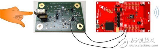
Important Safeguards
When using any electrical appliance, in order to reduce the risk of fire, electric shock and/or injury to persons, basic safety precautions should always be follow8d. including:
• The appliance is for household and indoor use only.
• Before plugging in. check that the voitage on the rating label is the same as the mains supply.
• To protect against electric shock, do not immerse any part of the product in water or other liquid.
• This socket is intended for use by competent adults only and children should be supervised at all times.
• Do not use the socket for other than its intended use.
• This socket can be used by children aged from 8 years arxl above and persons with reduced physical, sensory or mental capabilities or lack of experience and knowledge if they have been given supervision or instruction concerning use of the appliance in a safe way and understand the hazards involved. Children shall not p<ay with the appliance Cleaning and user maintenance shall M be made by children without supervision.
• Children of less than 3 years should be kept away unless continuously supervised.
Children from 3 years and less than 8 years shall only switch on/off the appliance provided that it has been placed or installed in its intended normal operating position and they have been supervision or instruction concerning use of the appliance in a safe way and understand the hazards involved. Children aged from 3 years and less than 8 years shall not plug in. regulate and clean the appliance or perform user maintenance.
• Don't use this socket in the immediate surroundings of a bath, a shower or a swimming pool.
• In case of malfunction, do not try to repair the socket yourself, it may result in a fire hazard or electric shock
Do Not Exceed Maximum a680W
Place the LR44 batteries provided into the compartment in the back of the Remote Control, please insert as sho*/m in the back of the compartment to ensure the polarity is correct.
• Plug the Remoce Socket$($)lnto the wall socket(s) and switch on the mams supply, the red LED will flash every second.
• If the LED is not flashing press & hold the manual ON/OFF button for 5 seconds until it Hashes
• Any number of Remote Sockets can be programmed to one Remote Control ON button to create multiple switching.
• To programme o<her Remote Sockets on different Remote Control ON buttons repeat the prevous steps
• If the mains supply is turned off the Remote Sockets v/ill lose their code and it wil be necessary to re-pcogramme.
Operation:
• Plug your appliance(s) into the Remote Socket(s)
• Press the programmed ON or OFF button on the Remote Control to control the Remote Socket.
♦ The Remote Sockets can also be operated manually using its ON/OFF Button Trouble shooting
If a Remote Socket does not react to the Remote Control please check the followng:
♦ Low battery in tbo Remote Control
• Distance too large between the remote control and the recerver (ensure the range distance is no more than 20 clear Metres) and free from obstacle that may reduce the distance.
• If programming has not been successful, tum the power off and back on then follow the programming steps above.
How to decode
• Press the manual ONX)FF button for 5 seconds until the red LED flashes once per
second to confirm de-coding is successful
♦ Press the ALL OFF switch on the Remote Control for more than 3 seconds, the LED
flashes once per second to confirm (decoding successful.
Voltage: 240V-/50HZ
Max power rating: 3680W max.
Remote frequency:
Remote range:
Battery Type:
433.92MHz
230 Metres
Button Cell 2x1.5V LR44 =
Please check with your local waste management service authority regarding regulations for the safe disposal of the batteries. The batteries should never be placed G municipal waste.
Use a battery d^posal facility if available
M
For eioctncal products sold within the European Community. At the end of the electrical products useful life, it should not be disposed of wth household waste. Please recycle faaMies exist. Check with your Local Authonty or retailer for recycling advice.
C€