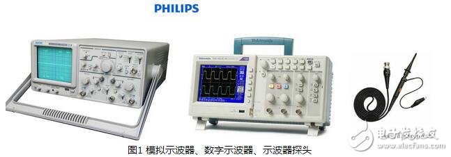
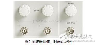
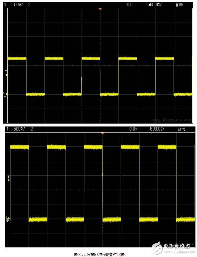
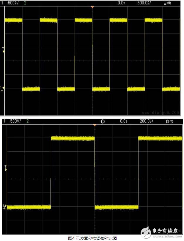
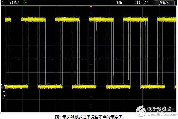
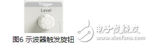
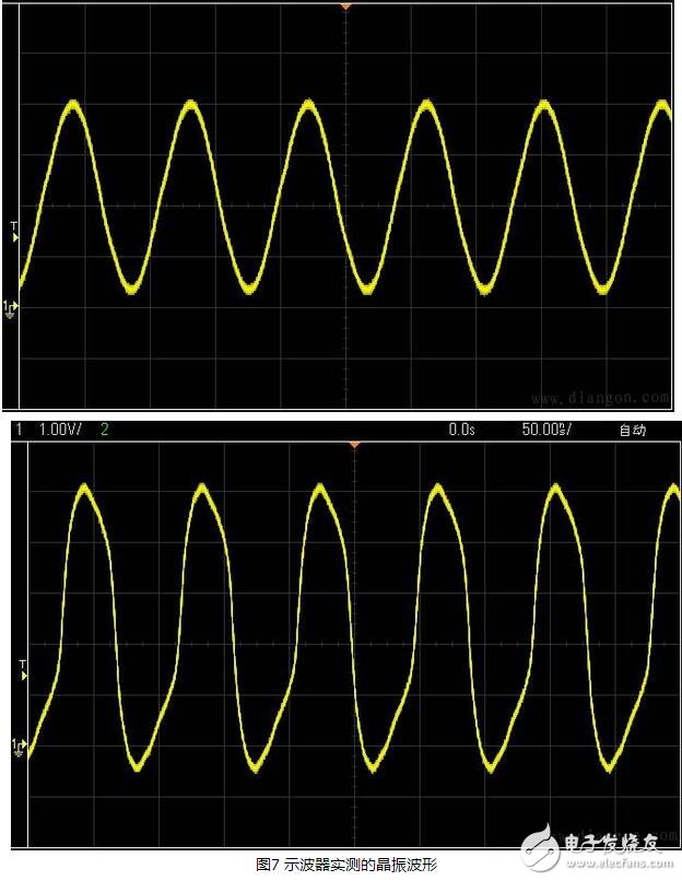
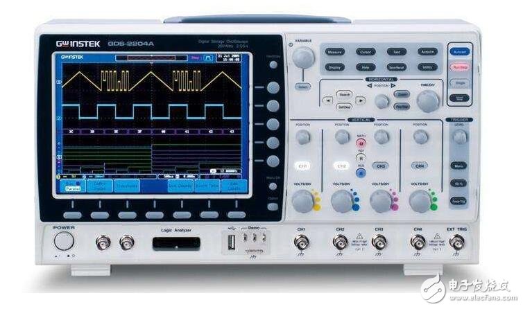
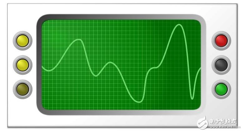
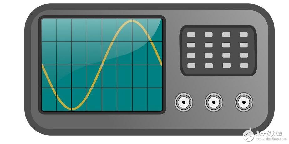
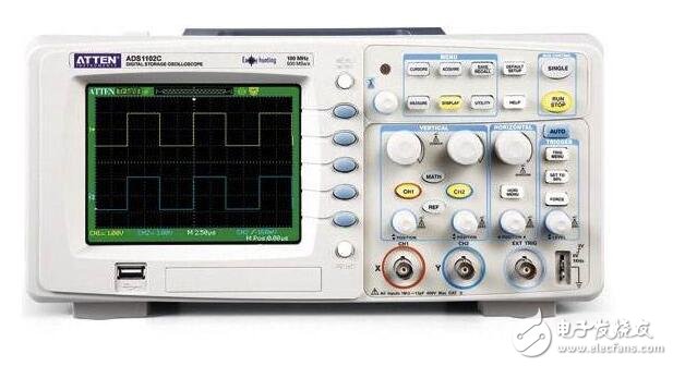
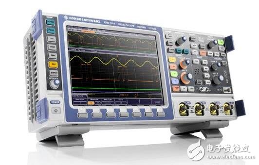
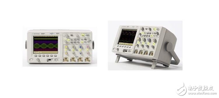
An oscilloscope is a widely used electronic measuring instrument. It can transform the electrical signals that are invisible to the naked eye into visible images, so that people can study the changes of various electrical phenomena. The oscilloscope uses a narrow beam of high-speed electrons to create a tiny spot on a phosphor-coated screen (this is how traditional analog oscilloscopes work). Under the action of the signal under test, the electron beam is like the tip of a pen, which can plot the instantaneous value of the measured signal on the screen. The oscilloscope can be used to observe waveforms of various signal amplitudes over time, and can also be used to test various types of power, such as voltage, current, frequency, phase difference, amplitude, and so on. An oscilloscope, "human", as its name suggests, is a machine that displays waveforms. It is also known as the "eye of an electronic engineer." Its core function is to display the actual waveform of the signal under test on the screen for engineers to find positioning problems or evaluate system performance and so on. Its development has also experienced the two eras of analog and digital, or first look at the picture to see, as shown in Figure 1. At present, analog oscilloscopes have basically been eliminated, and now it is the world of digital oscilloscopes. For the same reason, I will only use the digital oscilloscope as an example to explain. A more accurate name for a digital oscilloscope is a digital storage oscilloscope, DSO (Digital Storage Oscilloscope). This "storage" does not mean that it can store waveforms on a medium such as a USB flash drive, but rather for the instant display characteristics of an analog oscilloscope. An analog oscilloscope relies on a cathode ray tube (CRT, commonly known as an electron gun) that emits an electron beam that deflects under the magnetic field formed by the signal under test, thereby reflecting the waveform of the signal under test on the screen. This process is instant, without any stored procedures in between. The principle of digital oscilloscope is this: First, the oscilloscope uses the front-end ADC to quickly sample the measured signal. This sampling speed can usually reach several hundred M to several G times per second, which is quite fast; The display component of the end is a liquid crystal screen, and the refresh rate of the liquid crystal screen is generally only tens to hundreds of Hz; thus, the data sampled by the front end cannot be reflected to the screen in real time, so the storage is born: the oscilloscope samples the front end. The incoming data is temporarily stored in the internal memory, and the data is read in the memory when the display is refreshed. This level of storage is used to resolve the speed difference between the front-end sampling and the back-end display. When many people see the oscilloscope for the first time, they may be caught by the numerous buttons on his panel. In addition, the oscilloscope is generally worth more, so it has a fear of using it. This is unnecessary, because the oscilloscope looks complicated, but actually uses its core function - display waveforms, not complicated, as long as three or four steps can be done, and now the oscilloscope is complicated because Along with a lot of auxiliary functions, these auxiliary functions naturally have their value. Skilled and flexible application can achieve twice the result with half the effort. As a beginner, we don't care about this. We only apply its core and most basic functions. Similar to a multimeter, to use an oscilloscope, you must first connect it to the system under test, using an oscilloscope probe, as shown in Figure 20-4. Oscilloscopes usually have 2 or 4 channels (usually labeled with numbers from 1 to 4, and the extra probe socket is externally triggered, generally not used). Their low positions are equivalent and can be chosen at will. The probe is inserted into one of the channels, and the small clip on the other end of the probe is connected to the reference ground of the system under test. (There must be a problem here: the clip on the oscilloscope probe is directly connected to the ground, that is, the ground wire on the plug. If there is a voltage difference between the reference ground of the system under test and the ground, it will cause damage to the oscilloscope or the system under test. The probe touches the measured point, so that the oscilloscope can collect the voltage waveform at that point (ordinary The probe cannot be used to measure current, and the current probe must be selected for the current measurement. Next, adjust the waveform on the oscilloscope panel to display the measured waveform on the screen in an appropriate size. You only need to adjust the parameters of the oscilloscope according to the two major elements of a signal—magnitude and period (the frequency is conceptually equivalent to the period), as shown in Figure 2. As shown above, the knob above each channel socket adjusts the amplitude of the channel, that is, the adjustment of the vertical direction of the waveform. Turn them to change the voltage value represented by each vertical grid on the oscilloscope screen, so it can be called the "volt" adjustment, as shown in the following two comparison charts: 1V/grid on the left and 500mV on the right. /grid, the amplitude of the waveform on the left occupies 2.5 divisions, so it is 2.5V, and the amplitude of the waveform on the right shows 5 grids, which is also 2.5V. The recommendation is to adjust the waveform to the right, because the waveform occupies a large space in the entire measurement range, which can improve the accuracy of the waveform measurement, as shown in Figure 3. In addition to the usual Volge knob above Figure 3, a similarly sized knob (not necessarily the position shown in Figure 20-6) is usually found on the panel. This knob is the adjustment period, that is, the horizontal direction of the waveform. Adjustment. Turn it to change the time value represented by each horizontal grid on the oscilloscope screen, so it can be called the “second grid†adjustment, as shown in the following two comparison diagrams: 500us/grid on the left and 200us on the right. /grid, the left picture takes 2 cells, the period is 1ms, that is, the frequency is 1KHz, and the right picture takes 5 cells, which is 1ms, that is, 1KHz. There is no more reasonable question here. The specific problems are treated in a concrete way, as they are very reasonable, as shown in Figure 4. In many cases, only the above two adjustments can be made, but a waveform can be seen, but the waveform is very unstable, and the left and right trembles and overlap each other, resulting in invisibility, as shown in Figure 5. This is because the trigger of the oscilloscope is not adjusted well, so what is the trigger? Simply understand, the so-called trigger is to set a benchmark, so that the waveform is collected and displayed around this benchmark. The most commonly used trigger settings are level-based (also based on other quantities such as time, the same reason), let's look at the above waveforms, there is always a T and a small arrow on the left side, T is the meaning of the trigger The voltage value corresponding to the position pointed by this small arrow is the current trigger level. The oscilloscope always stores and displays the previous and subsequent parts as the waveform passes this level, so that the waveforms shown in Figures 4 and 5 can be seen. As shown in Figure 6, we can see that the waveform will not pass the position indicated by T anyway, that is, the trigger level will never be reached, so the waveform that has lost the reference looks unstable. How to adjust the position of this trigger level, find a knob labeled Trigger on the oscilloscope panel, as shown below, turn this knob to change the position of this T. In addition to changing the value of the trigger level, you can also set the trigger mode: for example, select the rising edge or the falling edge trigger, that is, select the trigger level when the waveform is increased upwards or the trigger level or the downward direction. To complete the trigger, these settings are usually done through the buttons in the Trigger bar and the convenient menu buttons on the screen. As long as the above three or four steps, you can apply the core functions of the oscilloscope, you can use it to observe the various signals of the microcontroller system. For example, if the system does not run after power-on, use it to test whether the waveform of the crystal pin is normal or not. It should be noted that the waveform on the crystal pin is not a square wave, but more like a sine wave, and the waveform on the two legs of the crystal is not the same. A small amplitude is used as an input, a frame. The larger value is output as shown in Figure 7. An instrument used to measure the shape of an alternating current or pulsed current wave, consisting of a tube amplifier, a scanning oscillator, a cathode ray tube, and the like. In addition to observing the waveform of the current, it is also possible to measure the frequency, voltage intensity, and the like. Periodic physical processes that can become electrical effects can be observed with an oscilloscope. Oscilloscopes are divided into digital and analog oscilloscopes. The analog oscilloscope uses an analog circuit (oscilloscope tube, which is based on an electron gun). The electron gun emits electrons to the screen, and the emitted electrons are focused to form an electron beam and hit the screen. The inner surface of the screen is coated with a fluorescent substance so that the point hit by the electron beam emits light. The digital oscilloscope is a high-performance oscilloscope manufactured by a series of technologies such as data acquisition, A/D conversion, and software programming. Digital oscilloscopes generally support multi-level menus, which can provide users with multiple choices and multiple analysis functions. There are also oscilloscopes that provide storage for saving and processing waveforms. The working principle of the oscilloscope is to reflect the relative magnitude of the maximum value of the voltage applied to the yaw deflection plate of the oscilloscope by using the relative magnitude of the amplitude of the waveform displayed on the oscilloscope, thereby reflecting the maximum value of the alternating electromotive force generated in the electromagnetic induction. size. Therefore, the relationship between the induced electromotive force and its generating conditions can be studied by means of an oscilloscope. An oscilloscope is a widely used electronic measuring instrument. It can transform the electrical signals that are invisible to the naked eye into visible images, so that people can study the changes of various electrical phenomena. The oscilloscope uses a narrow, electron beam of high-speed electrons to create a tiny spot of light on a phosphor-coated screen. Under the action of the signal under test, the electron beam is like the tip of a pen, which can plot the instantaneous value of the measured signal on the screen. The oscilloscope can be used to observe the waveforms of various electrical signals with varying amplitudes over time. It can also be used to test the power of various signals, such as voltage, current, frequency, phase difference, amplitude, and so on. The dual-track oscilloscope is a two-channel y-axis preamplifier circuit, a gate circuit, an electronic switch, a hybrid circuit, a delay circuit, a y-axis post-amplifier circuit, a trigger circuit, a scan circuit, an x-axis amplifier circuit, and a z-axis amplification. Circuit, calibration signal circuit, oscilloscope tube and high and low voltage power supply circuit. When observing the signal waveform, the measured signals UA and UB are input to the oscilloscope through the two input terminals of CHA and CHB, and are respectively sent to the y-axis preamplifier circuits yA and yB for amplification. Since the channel yA and the channel yB are both controlled by the electronic switch, the UA and UB signals are alternately transmitted to the subsequent hybrid circuit, the delay circuit, and the y-axis post-amplifier circuit, and are applied to the vertical deflection plate of the oscillating tube. In order to adapt to various test needs, the electronic switch can have five different working states, namely CHA, CHB, alternating, intermittent, ADD and so on. These five operating states are controlled by the display mode switch. When the display mode switch is placed in an alternate position, the electronic switch is a bistable circuit. It is controlled by the gate signal from the scanning circuit so that the two front channels of the y-axis follow the scanning circuit. The gate signal changes alternately to work. The number of alternate conversions per second is related to the repetition frequency of the scan signal generated by the scanning circuit. The alternating working state is suitable for observing the measured signal whose frequency is not too low. When the display mode switch is placed in the intermittent position, the electronic switch is a self-excited multi-resonant circuit with an oscillation frequency of about 200 kHz. Two rectangular signals of opposite phases are outputted by its two outputs. The preamplifier circuits CHA and CHB are operated in turn by the control of the above two rectangular signals. This will allow two signals to be displayed steadily. This intermittent working state is suitable for observing the measured signal with a frequency that is not too high. When the display mode switch is placed in the CHA or CHB position, the electronic switch is a monostable circuit. The preamplifier circuit CHA or CHB can work alone. At this time, the dual trace oscilloscope can be used as a normal single line oscilloscope. When the display mode switch is placed in the ADD position, the electronic switch is not in operation. At this time, the two channels of CHA and CHB work simultaneously, so that the display of two signals addition or subtraction of two signals can be obtained. However, whether the two signals are added or subtracted is selected by the polarity action switch of the CHA channel. In order to observe the waveform of the signal being tested over time, the oscilloscope's horizontal deflection plate must be linearly scanned (sawtooth voltage). This scan voltage is generated by the scanning circuit. When the trigger signal is applied to the trigger circuit, the trigger scan circuit generates a corresponding scan signal. When the trigger signal is not applied, the scan circuit does not generate the scan signal. The trigger mode has an internal trigger and two external triggers, which are selected by the trigger source selection switch. When the switch is placed in the inner position, the trigger signal is from the measured signal sent through the y-axis channel, when the switch is placed outside. At the time of the position, the trigger signal is sent from the outside. This signal should be in an integer ratio to the frequency of the signal being measured. Most oscilloscopes use internal triggering. The scanning circuit generates a scanning signal (sawtooth circuit). The x-axis amplifying circuit is connected to the x-axis amplifying circuit, and is amplified and sent to the x-axis deflecting plate of the oscilloscope. The Z-axis amplifying circuit plays a role in adjusting the brightness of the spot on the screen, and erases the track of the spot that is not necessarily displayed. When the gate signal of the scanning circuit comes to the z-axis amplifying circuit, the z-axis amplifying circuit outputs a positive boosting pulse signal to the control pole of the oscilloscope. That is to say, in the forward direction of the scanning signal, the light spot on the fluorescent screen is enhanced. During the conversion process of the electronic switch, the electronic switching circuit adds the output pulse signal to the z-axis amplifying circuit, and the z-axis amplifying circuit at this time The negative pulse signal is output and added to the oscilloscope's gate. In the conversion process of the electronic switch, the excessive light spot when the two channels are alternately operated is eliminated, so as to improve the definition of the display waveform. The correction signal generating circuit generates a rectangular signal of a certain frequency and amplitude. It is used to correct the sensitivity of the y-axis amplifier circuit and the scan speed of the x-axis. High and low voltage power supplies, where high voltage is supplied to the oscilloscope display system. Low voltage is supplied to the oscilloscope stages. The differential probe pair is matched to the differential amplifier and equalized to the attenuation factor to improve the maximum input signal and common mode range. The system can perform the test function of the factory: power device analysis, and Figure 2 shows the test of instantaneous power. In addition, for the safe working area of ​​the device, dynamic on-resistance and other related performance analysis can be measured with the system, just a few key presses can be completed. Modulation analysis, Figure 3 shows the device's confidence and state during the conversion process. Just try the system diagram Digital oscilloscope can effectively observe and analyze various waveforms, and can also display various "analog parameters", coupled with appropriate external equipment to connect "l, it is easy to capture such as load changes, power switch A complete record of each cycle and a detail of the important circuit conversion, so as to obtain real-time analysis of the realistic image of various test data. Power measurement software provides the necessary means for intelligent testing of the instrument. Support in the hardware circuit Relying on the program software to improve the functions in an orderly and coordinated manner. Users can easily set up the oscilloscope by using special menus and shortcuts to sample, observe, analyze signals and intelligent prompts to ensure correct and accurate measurement. The frequency response of the differential amplifier is 100MHz. The gain can be set to 1 or 10. As part of the oscilloscope side test system, it can not only adjust the signal, but also improve the input impedance and common mode rejection ratio. The panel of the amplifier accepts remote control commands or RS232 control. It measures the current flowing through the conductor. The analysis shows each pulse on the vertical axis. Pulse width value, stable observation soft-start circuit characteristics 'à monitor 5 volt power supply from volts to stable +5 process amplification function allows lining each gate drive pulse independent observation diagram circuit device working state test analysis power supply designer can be concise Visually observe various information states such as duty cycle, period, pulse width, step response, etc. Line power measurement and analysis: For analog signals such as power frequency voltage, it is convenient to measure its power factor and power consumption. , voltage and current rms, and harmonic measurements. The magnified trajectory can be used to magnify or carry out other waveforms. For example, the oscilloscope function of a digital oscilloscope can be used to display an energy waveform immediately (the Joules are chosen as the O or the 6OH. The effective power of the frequency current depends on the power factor. “Real-time waveforms. Figure 4: Line power test analysis. Figure 2: Instantaneous power. The test oscilloscope can also calculate power with J2. The two waveforms shown in the upper part of Figure 5 represent the power supply. When the input voltage is loaded with the voltage waveform and current waveform, the performance of the wireless communication system is stronger and the power consumption is lower. When selecting a processing engine for a wireless design such as a mobile phone, the designer has to be careful. With the development of mobile phones to the third generation and even the fourth generation, designers have begun to develop some new features such as video functions. Traditional microprocessor-based and DSP-based wireless design solutions are already lacking in strength. On the other hand, adaptive computer (ACM) devices can provide a more efficient way for wireless system design. In order for the RISC microprocessor core to match the fine adaptive structure, this is an early prototype of an adaptive computer that integrates a RISC processor core with a large-scale adaptive structure. Usually a DSP chip has a CPE of about 10%, which means that at any one time, only 10% of the logic gates in the DSP chip are used to perform the actual tasks, that is, only a small part of the "useful" work is done. The rest of the work is done in an auxiliary work. When the processor is busy with the actual work, this auxiliary work is required to occupy the processor's resources as little as possible.
Knowing which specific Mac model you have is important.
Please contact with me, that I can tell you about your Mac model and generation will be displayed.
macbook 85w charger,apple macbook 85w charger,85w charger for macbook pro Shenzhen Waweis Technology Co., Ltd. , https://www.waweis.com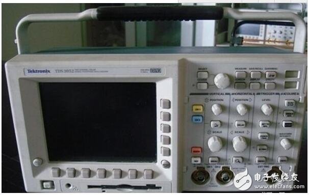

What is an oscture? How to use the oscilloscope, how the oscilloscope works
What is an oscture?
The 85W Macbook Charger MagSafe 1 or MagSafe 2 Power Adapter features a magnetic DC connector so if someone should trip over it, the cord disconnects harmlessly and your MacBook Pro stays put safely. It also helps prevent fraying or weakening of the cables over time. In addition, the magnetic DC helps guide the plug into the system for a quick and secure connection.
When the connection is secure, an LED located at the head of the DC connector lights up; an amber light lets you know that your notebook is charging, while a green light tells you that you have a full charge. An AC cord is provided with the adapter for maximum cord length, while the AC wall adapter (also provided) gives you an even easier and more compact way to travel.
Designed to be the perfect traveling companion, the adapter has a clever design which allows the DC cable to be wound neatly around itself for easy cable storage.
This power adapter recharges the lithium polymer battery while the system is off, on, or in sleep mode. It also powers the system if you choose to operate without a battery.
Compatible with MacBook Pro with Retina display.
Not sure if this is the right power adapter for your Mac?
See this article for more details about choosing the right one.