Figure 1 is a class A power amplifier, the load RL becomes the collector load RL = n through the impedance converter B Follow WeChat Download Audiophile APP Follow the audiophile class related suggestion Avago Introduces New High Linear Power Amplifier Module Product Avago Technologies ... The circuit is shown in Figure 1. The chip IC uses the LM1875 of the American NS company, which has a soft tone and low distortion (0.015% ... The word "Monster" has both positive meaning and ... When the output power of the digital power amplifier is greater than 50W, it is impossible to use only ... If an "audiophile" is a group of people who are never satisfied with the sound and "loved the new and the old" with the audio equipment. Then just rely on these so-called "fever spirits" ... First, the circuit principle and characteristics 1. Power amplifier part (see Figure 1) There is a well-known saying in the Hi-Fi world that is "briefness first." This means that if ... Simple and practical TDA2822M integrated power TDA2030 is ... STK465 thick film ... This RF power amplifier can output 2-3 channel signals, covering an area of ​​about one square kilometer, is ... Looking at the Hi-Fi amplifiers currently on the market, the output power is 100W ... With the newly launched LM4651 and LM465 from National Semiconductor ... EL34 (6CA7) was first launched by Philips in 1956 ... This article cleverly combines the electronic tube EL34 and the transistor (op amp), ... The pre-amplifier adopts a European-made TESLA brand low noise high cheek double transistor ... "Simple" means the circuit of the amplifier is simple, making it easier, as long as the picture ... 1. Description: & nb ... The Class A transistor power amplifier has a warm and sweet tone, which makes people tempted. But the temperature rise of Class A amplifier ... The circuit is shown in Figure 5, ... '+ data.data.username +' '; dom + =' A business tablet must have powerful business functions. At present, users use tablet products more for entertainment, and insufficient development of commercial value has become a major factor restricting the development of tablet computers. Many far-sighted terminal manufacturers have set their sights on the business tablet field. Business Tablet,4k Tablet,5G Tablet Jingjiang Gisen Technology Co.,Ltd , https://www.jsgisentec.com Power amplification is an energy conversion circuit. Under the effect of the input signal, the transistor converts the energy of the DC power supply into output power that varies with the input signal to the load. The requirements for power amplification are as follows:
(1) The output power should be large: To increase the output power of the amplifier, the transistor must be operated near the limit working area, which is determined by ICM, UCM and PCM. See Figure 1. 
Figure 1 (2) The efficiency η is higher: the efficiency η of the amplifier is defined as: η = AC output power / DC input power (3) The nonlinear distortion is within the allowable range: Because the power amplifier works under a large signal, nonlinear distortion is inevitable The problem is to control the distortion within the allowable range,
The power amplifier can be divided into the following types according to the working state and circuit form:
(1) Class A power amplifier: During the entire signal period, there is collector current;
(2) Class B power amplifier: within half a signal period, there is a collector current, which can be divided into:
1) Double-ended push-pull circuit (DEPP)
2) Single-ended push-pull circuit (SEPP)
3) Balanced transformerless circuit (BTL)
In practice, in order to overcome the crossover distortion, the push-pull Chang body tube circuit is working in Class A and B states. 1. Class A power amplifier RLo For DC, the primary DC resistance of transformer B and Re are very small, so the DC load line is close to a vertical line. See Figure 1 (b). To make the amplifier output more power, the AC load line can be placed at a and b Position: Uce = UCM at point a, and the operating point Q is at the midpoint of ab straight line. Usually the saturation voltage drop and penetration current of the transistor are very small. And voltage amplitude are:
Icm = IcM / 2, Ucem = UCM / 2 --------------------------------------- ---------Formula 1
The AC power (or amplifier output power) of the load is:
PL = (UceM / ) × (IcM /
) = (IcM /
) × (UcM /
) = (1/8) IcM × UcM ------ Equation 2
The collector current ICQ and voltage UceQ of operating point Q are:
ICQ = ICM / 2, UceQ = Ec = UCM / 2 ------------------------------------- -------- Form 3
Therefore, the input power of the DC power supply:
PD = IcQ × UceQ = (ICM / 2) × (UCM / 2) = 1 / 4IcMUcm ----------------------------- --Form 4
The efficiency of the Class A power amplifier is:
η = PL / PD = 50% ------------------------------------------ --------------- Form 5 It can be seen that: (1) The maximum collector voltage of the transistor is twice the power supply voltage EC.
(2) The static power consumption of the transistor is twice the output power.
(3) The maximum efficiency of Class A amplifier is only 50%. 2. Class B push-pull circuit Figure 2 (a) is a class B push-pull circuit. Because the output uses a transformer, the transistor has two output terminals to ground. The circuit is completely symmetrical. When the input signal Us is a positive half wave, BG1 is turned off and BG2 is turned on. The voltage UL is a negative half-wave. Therefore, the two tubes are turned on in turn and work with one push and one pull, so it is called a push-pull circuit.
Since the two tubes work alternately, the output characteristics of the two tubes are stacked together in opposite directions. The AC load lines of the two tubes are connected in a straight line ab, and the operating point Q is at the midpoint of the straight line ab, as shown in Figure 2 (b). It can be seen from the figure that the relationship between the amounts of electricity:
(1) If the turns ratio of the primary and secondary windings of the output transformer is n, then the load resistance RL of each transistor is:
RL = (n / 2) RL = (n
/ 4) RL -------------------------------------------- Equation 6
The resistance RCC between the collector and the collector is
Rcc = n RL = 4RL ----------------------------------------------- ------ Form 7
(2) The voltage amplitude of the primary winding end of transformer B2 is:
Ucem = UceQ≈Ec --------------------------------------------- ------- Form 8
The primary winding current amplitude is:
Icm = IcM ----------------------------------------------- ----------- Form 9
So the power delivered to the primary winding is:
Ps = (Ucem / ) × (Icm /
) = (1/2) EcIcm ------------------------------ Equation 10
(3) The average value of the current through each transistor is:
Ico = IcM / π --------------------------------------------- ---------- Form 11
The power supplied by the DC power supply is
PD = (2Ico) Ec = 2 × (Icm / π) × Ec ---------------------------------- ---- Form 12
(4) The efficiency of the push-pull circuit is:
η = (Ps / PD) 100% = {(1/2 × Ec × Icm) / [2 × (Icm / π) × Ec]} 100% ≈78.5% ----- Equation 13
Pay attention to when designing the push-pull circuit:
(1) To avoid crossover distortion, the transistor should have a certain bias current, but not too large, otherwise the circuit efficiency will be reduced.
(2) The maximum collector voltage of the transistor Ucm> 2Ec.
(3) The dissipated power of the transistor Pcm≥1.2Pc1, where Pc1 is the power that each transistor sends to the transformer B2 primary, that is, Pc1 = [(1/2) Pso].
(4) According to the requirements of Pc1 and Ec1, calculate the transistor load resistance PL and the turns ratio n of the output transformer. 
figure 2 


![[Photo] 15w RF power amplifier](http://i.bosscdn.com/blog/20/06/41/521040781.gif)
![[Photo] Broadband high frequency power amplifier](http://i.bosscdn.com/blog/20/06/41/520536801.jpg)
![[Photo] TDA2030 audio power amplifier](http://i.bosscdn.com/blog/20/06/41/5131012891.gif)
![[Photo] Transistor 15W Class A Power Amplifier](http://i.bosscdn.com/blog/20/06/41/513102891.gif)
![[Photo] 125W Class D Subwoofer Power Amplifier](http://i.bosscdn.com/blog/20/06/41/513100868.jpg)
![[Photo] Mark Levinson No. 30 ...](http://i.bosscdn.com/blog/20/06/41/513544752.jpg)
![[Photo] 45W transistor tube hybrid power amplifier](http://i.bosscdn.com/blog/20/06/41/513531952.jpg)
![[Photo] 32W hybrid audio power amplifier](http://i.bosscdn.com/blog/20/06/41/513526493.jpg)
![[Photo] Gallstone hybrid power amplifier using switching power supply](http://i.bosscdn.com/blog/20/06/41/513524776.gif)
![[Photo] Simple fool power amplifier](http://i.bosscdn.com/blog/20/06/41/513432946.jpg)
![[Photo] LM386 low voltage audio power amplifier ...](http://i.bosscdn.com/blog/20/06/41/513417261.gif)
![[Photo] Class A power amplifier using SAP15N / P audio pair tube ...](http://i.bosscdn.com/blog/20/06/41/513346769.gif)
![[Photo] Using TDA7294 and 2SA1216 / 2S ...](http://i.bosscdn.com/blog/20/06/41/4233420295.gif)
'+ data.username +'
'+ data.username +'
'; dom + ='
'; $ (' # follow_list '). append (follow_user);} if (data.status == "failed") {alert (data.msg);}});} else {// Unfollow if ($ ( this) .attr ('id') == 'cancelFollow') {$ .post ('/ d / user / cancelFollow', {tuid: article_user_id}, function (data) {// Data format returned: if (data .status == "successed") {follow_wrap.html ('Follow'). attr ('id', 'follow'). css ('background', '# f90'); $ (". followNum strong"). html (-getFollowNum); $ ('# follow_list .face'). each (function () {var target_uid = $ (this) .attr ('data-uid'); if (target_uid == now_uid) {$ ( this) .remove ();}})} if (data.status == "failed") {alert (data.msg);}}); return false;}}});});}); / * var myface = "{$ _super ['uid'] | avatar}"; var myname = "{$ _super ['username']}"; var article_id = {$ article ['id']}; var article_user_id = {$ article ['mid']}; // Article author ID $ (function () {<notempty name = "clearnum"> // Reduce the number of reminders var count = parseInt ($ ("# noticeCount"). html ()); count = count-{$ clearnum}; $ ("# noticeCount"). html (count); if ( count
Generally speaking, when business users choose tablet PC products, they still focus on "regular items" such as processor, battery, operating system, and built-in applications, especially office software applications, which are a good helper for business users.
First of all, there must be powerful office software such as customer management software, which can record customer data and related information anytime, anywhere. There is also a need for powerful marketing software, software marketing, reducing manual intervention, and one person can handle all the publicity and customer information.
Low frequency power amplifier
Low frequency power amplifier
Interesting and informative information and technical dry goods
Create your own personal electronic circle
Lock the latest course activities and technical live broadcast
comment
Publish
Avago introduces new high linear power amplifier module products
Published on 2010-03-12 11:01 • 325 views
Using LM1875 and 2SA1943 / 2SC5200 ...
Posted at 2006-04-17 23:28 • 2226 views
Appreciate a variety of giant power amplifiers
Posted at 2006-04-17 23:27 • 1406 views
100W Digital Power Amplifier Made with Gate Driver IC
Published on 2006-04-17 23:27 • 995 views
Detailed explanation of class AB power amplifier
Published on 2006-04-17 23:27 • 6112 views
Transistor 15W Class A power amplifier
Published on 2006-04-17 23:26 • 1261 views
"Simple first" transistor Class A audio power amplifier
Published on 2006-04-17 23:26 • 4341 times read
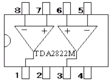
Simple and practical TDA2822M integrated power amplifier
Published on 2006-04-17 23:25 • 2750 views
TDA2030 audio power amplifier
Published on 2006-04-17 23:22 • 1049 views
STK465 audio power amplifier
Published on 2006-04-17 23:22 • 4311 reading
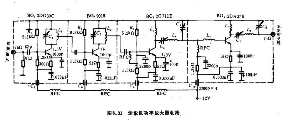
Video Recorder RF Power Amplifier
Published on 2006-04-17 19:10 • 275 times read
[Photo] 15w RF power amplifier
Published on 2006-04-15 21:00 • 440 views
[Photo] Broadband high frequency power amplifier
Published on 2006-04-15 20:53 • 802 views
[Photo] TDA2030 audio power amplifier
Published on 2006-04-15 13:10 • 1249 times read
[Photo] Transistor 15W Class A Power Amplifier
Published on 2006-04-15 13:10 • 1306 times read
[Photo] 125W Class D Subwoofer Power Amplifier
Posted at 2006-04-15 13:10 • 337 views
[Photo] Mark Levinson No. 30 ...
Posted at 2006-04-15 13:05 • 1336 views
[Photo] 45W transistor tube hybrid power amplifier
Published on 2006-04-15 13:05 • 1443 views
[Photo] 32W hybrid audio power amplifier
Published on 2006-04-15 13:05 • 1312 views
[Photo] Gallstone hybrid power amplifier using switching power supply
Published on 2006-04-15 13:05 • 1092 times read
[Photo] Simple fool power amplifier
Posted at 2006-04-15 13:04 • 2479 views
[Photo] LM386 low voltage audio power amplifier ...
Posted at 2006-04-15 13:04 • 1397 times read
[Photo] Class A power amplifier using SAP15N / P audio pair tube ...
Published on 2006-04-15 13:03 • 3767 views
[Photo] Using TDA7294 and 2SA1216 / 2S ...
Published on 2006-04-14 23:34 • 3043 times read