From the comparison between the plc control system and the electrical control system, the PLC user program (software) replaces the relay control circuit (hardware). Therefore, for the user, the PLC can be equivalent to a large variety of "soft relay" and "soft wiring", and the user program uses "soft wiring" to "soft relay" and The "control circuit" whose "contact" is connected according to certain requirements. In order to better understand this equivalent relationship, the following is illustrated by an example. Figure 1 shows the electrical control system for the one-way starting operation of a three-phase asynchronous motor. Among them, the input of the input device SB1, SB2, FR constitutes the input portion of the system, and the output device KM constitutes the output portion of the system. Insulated Power Cable,Bimetallic Crimp Lugs Cable,Pvc Copper Cable,Cable With Copper Tube Terminal Taixing Longyi Terminals Co.,Ltd. , https://www.longyicopperterminals.com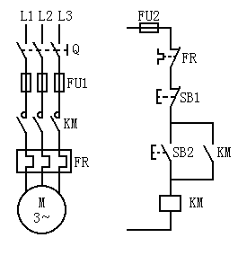 Fig.1 Three-phase asynchronous motor one-way operation electrical control system diagram, the input devices SB1, SB2, FR correspond to the "coils" of the "soft relays" X0, X1, X2 inside the PLC, and the corresponding "soft" is controlled by the input device The state of the relay, that is, the state of the external input device is changed to the internal state of the PLC through these "soft relays". This kind of "soft relay" is called the input relay; similarly, the output device KM and the "soft relay" Y0 inside the PLC Correspondingly, the state of the corresponding output device KM is controlled by the "soft relay" Y0 state, that is, the PLC internal state is output through these "soft relays" to control the external output device, and such "soft relay" is called an output relay. Therefore, the PLC user program is to achieve: how to use the input relays X0, X1, X2 to control the output relay Y0. When the control requirements are complicated, other types of "soft relays" inside the PLC, such as auxiliary relays, timers, counters, etc., are used in the program to achieve control requirements.
 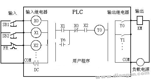 Figure 2 PLC equivalent circuit a) Main circuit b) Control circuit If PLC is used to control this three-phase asynchronous motor to form a PLC control system, according to the above analysis, the main circuit of the system is unchanged, as long as the input device SB1 The contacts of SB2 and FR are connected to the input end of the PLC, and the output device KM coil is connected to the output end of the PLC to form the input and output hardware lines of the PLC control system. The function of the control part is realized by the user program of the PLC, and its equivalent circuit is shown in Figure 2.