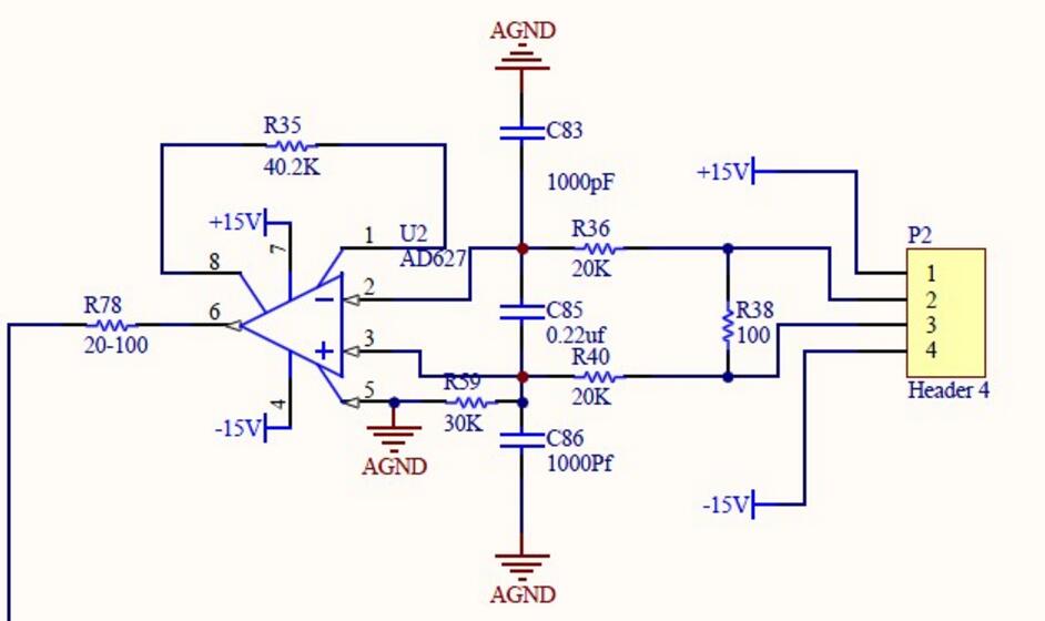
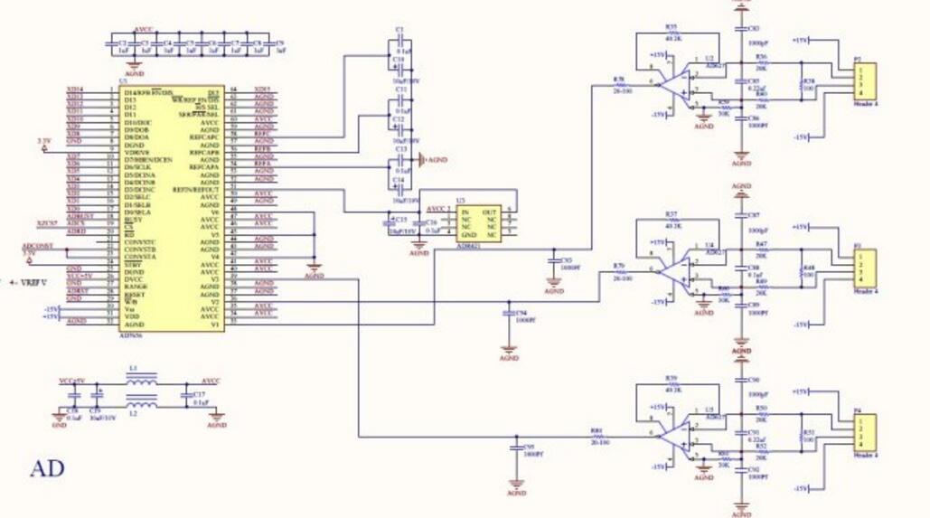
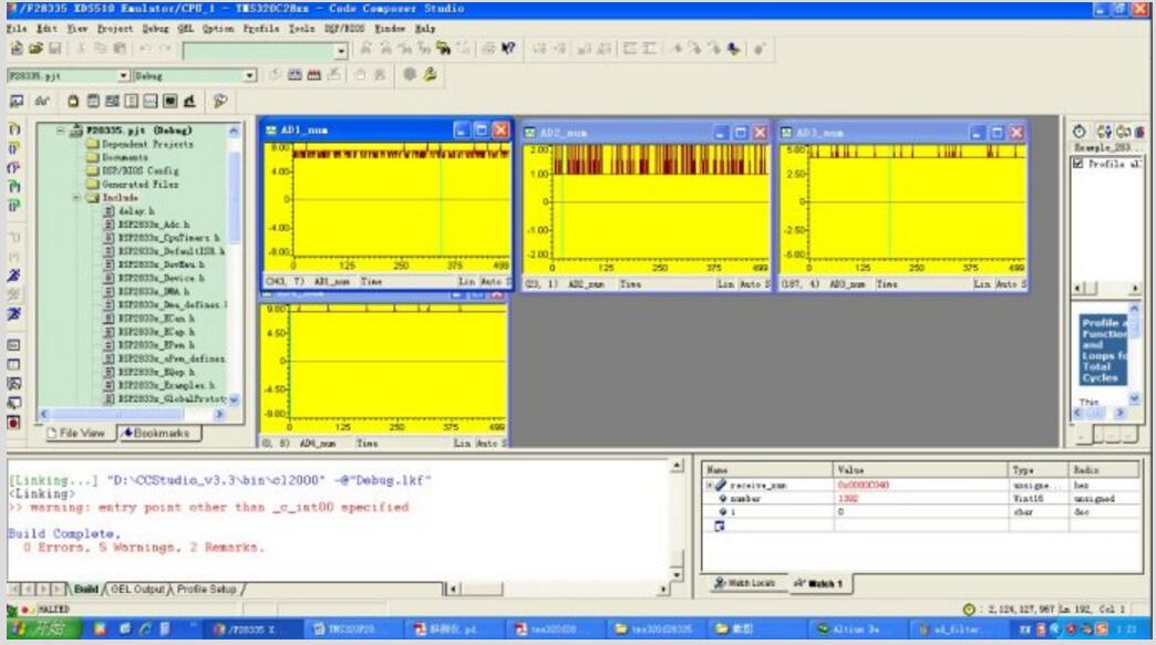
The TMS320F28335 is a TI high-performance TMS320C28x family of 32-bit floating-point DSP processors. TMS320F28335 digital signal processor TI's TMS320C28X series of floating-point DSP controller. Compared with the conventional fixed-point DSP, the device has high accuracy, low cost, low power consumption, high performance, high peripheral integration, large data and program storage, and more accurate and fast A/D conversion. TMS320F28335 has 150MHz high-speed processing capability, 32-bit floating point processing unit, 6 DMA channels to support ADC, McBSP, and EMIF. There are up to 18 PWM outputs, among which 6 channels are TI's unique high-precision PWM output. (HRPWM), 12-bit, 16-channel ADC. Thanks to its floating-point unit, users can quickly write control algorithms without spending too much time and effort on fractional operations. Compared to previous generation DSPs, the average performance is improved by 50%, and with the fixed-point C28x controller software Compatibility, simplifying software development, shortening development cycles, and reducing development costs. TMS320F28335 (SOM-TL28335 core board) working environment Environmental Parameters\Minimum\Typical Value\Maximum Industrial temperature: 0°C\-\85°C Operating voltage: 4.8V\5V\5.5V SOM-TL28335 (TMS320F28335) core board power consumption Supply voltage: 5V Input current: 292mA Rated power: 1.46W TL28335-EVM Development Board Power Consumption Supply voltage: 5V Maximum input current: 400mA Maximum power: 2W Based on TMS320F28335 floating point DSP controller; TI's main high-performance TMS320C28x series DSP controller, the main frequency up to 150MHz; With I2C, SPI, eCAN, ePWM bus interface, suitable for a variety of control equipment; Small size, high performance, high portability, suitable for a variety of handheld devices; Meet the high and low temperature, vibration requirements, meet the industrial environment applications. The AD7656 integrates six 16-bit 250kpbs ADCs on chip, six true bipolar high-impedance analog inputs, allowing parallel or serial output, accelerometers with +-15V supply, output current signals from -20mA to 20ma, and conditioning circuits using the AD627 for conditioning Circuits, schematics have been designed as follows: P2 is an external acceleration sensor, 2 feet is the current output, and AD627 is a low-power instrumentation amplifier. It uses single and dual power supplies and can implement rail-to-rail outputs. The AD627 uses a true instrumentation amplifier architecture with two feedback loops. The basic structure is similar to that of a typical "double op amp" instrument amplifier, but the details are different. In addition, there is a "current feedback" structure that makes it have a good common-mode rejection ratio. In the figure, 20mA current changes to 2V after 100 ohm sampling resistance; AD627 does not connect R35, the gain is 5, so AD627 output is +-10V voltage, and then sent to AD. The wiring of the AD7656 is shown in the figure below: In the figure above, the three current signals are conditioned by the AD7656 and become voltage signals to the DSP. In the wiring of the circuit, the analog digital ground should be used to separate the wiring. After the magnetic beads are single-pointed, the entire circuit board is divided into an analog section and a digital section. Otherwise, it is difficult to meet the sampling accuracy requirements. Attached below is the 28335 driver for the AD7656 Void RESET_AD(void) { EALLOW; GpioCtrlRegs.GPAPUD.bit.GPIO4 = 1; // disable pullup on GPI4 GpioCtrlRegs.GPAMUX1.bit.GPIO4 = 0; // GPI4 = GPI4 GpioCtrlRegs.GPADIR.bit.GPIO4 = 1; // GPI4 = output GpioDataRegs.GPASET.bit.GPIO4 = 1; EDIS; Delay_us(100); EALLOW; GpioCtrlRegs.GPAPUD.bit.GPIO4 = 1; // disable pullup on GPI4 GpioCtrlRegs.GPAMUX1.bit.GPIO4 = 0; // GPI4 = GPI4 GpioCtrlRegs.GPADIR.bit.GPIO4 = 1; // GPI4 = output GpioDataRegs.GPACLEAR.bit.GPIO4 = 1; EDIS; } Void Start_Convert() { EALLOW; GpioCtrlRegs.GPAPUD.bit.GPIO0 = 1; // disable pullup on GPI0 GpioCtrlRegs.GPAMUX1.bit.GPIO0 = 0; // GPI0 = GPI0 GpioCtrlRegs.GPADIR.bit.GPIO0 = 1; // GPI0 = output GpioDataRegs.GPACLEAR.bit.GPIO0 = 1; EDIS; EALLOW; GpioCtrlRegs.GPAPUD.bit.GPIO0 = 1; // disable pullup on GPI0 GpioCtrlRegs.GPAMUX1.bit.GPIO0 = 0; // GPI0 = GPI0 GpioCtrlRegs.GPADIR.bit.GPIO0 = 1; // GPI0 = output GpioDataRegs.GPASET.bit.GPIO0 = 1; EDIS; } Void Wait_AD() { EALLOW; GpioCtrlRegs.GPAPUD.bit.GPIO2 = 0; // disable pullup on GPI2 GpioCtrlRegs.GPAMUX1.bit.GPIO2 = 0; // GPI2 = GPI2 GpioCtrlRegs.GPADIR.bit.GPIO2 = 0; // GPI2 = input EDIS; While(GpioDataRegs.GPADAT.bit.GPIO2 == 1); } Void start_AD(void ) { Start_Convert(); Wait_AD(); } Uint16 AD_read(void ) { Uint16 temp=0; Temp= AD7656_ADD; Return temp; } Void Get_Ad_Dat(void) // Collect all ad data { Int16 i=0,temp1; Int32 temp[3]={0,0,0}; For(i=0;i<<FILTERLEN;i++) { start_AD(); Temp1=AD7656_ADD; Temp[0]+=temp1; Temp1=AD7656_ADD; Temp[1]+=temp1; Temp1=AD7656_ADD; Temp[2]+=temp1; Temp1=AD7656_ADD; Temp1=AD7656_ADD; Temp1=AD7656_ADD; } AccDat.AD_x_cur[Counter]=temp[0]/FILTERLEN; AccDat.AD_y_cur[Counter]=temp[1]/FILTERLEN; AccDat.AD_z_cur[Counter]=temp[2]/FILTERLEN; } The following is the FILTERLEN=8 in the output waveform program when the input channels are grounded; It can be seen that after a simple digital processing, the AD7656 can achieve a 1-bit transition accuracy. The data in each channel in the above figure is not the same, and the gap is relatively large. We have not yet found the reason. UV Film,UV Screen Protector,UV Curing Screen Protector Shenzhen Jianjiantong Technology Co., Ltd. , https://www.jjtbackskin.com

TMS320f28335 controls the hardware circuit design of AD7656
TMS320F28335 Introduction