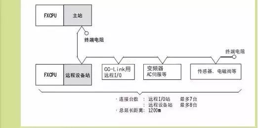
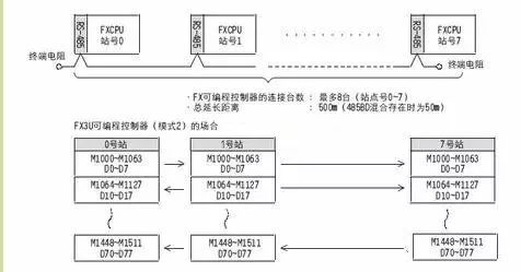
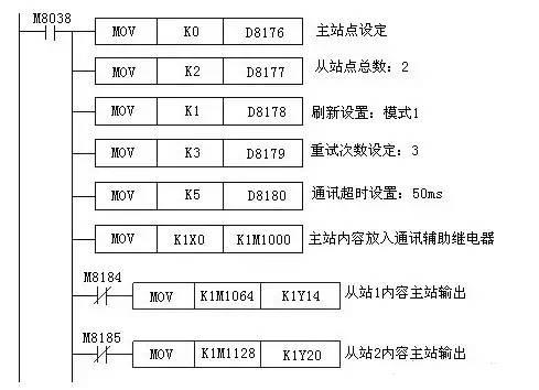
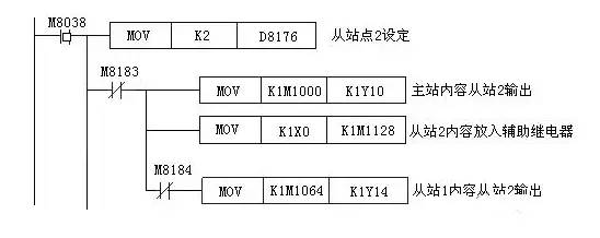
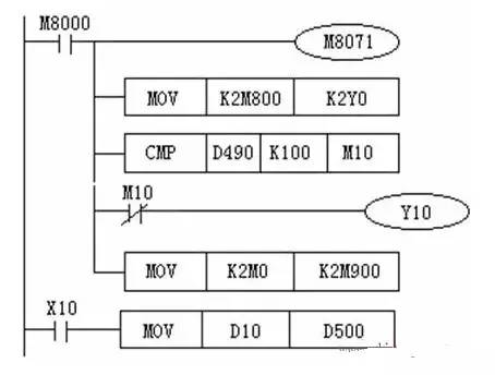
FX series as Mitsubishi's basic models PLC, the communication between them are as follows: CC-LINK, N: N network connection, parallel connection. The corresponding PLCs can be FX1N, FX1NC, FX2N, FX2NC, FX3U, FX3UC, because when CC-LINK communication is used, CC-LINK module needs to be expanded, and FX1S has no extension module function, so FX1S cannot be used for this communication method. 2) The FX1N/FX2N/FX3U can be used as a master station or as a remote device station. This kind of communication is costly due to the addition of CC-LINK communication modules. 3) In the CC-LINK network, it is also possible to add devices such as inverter servos that conform to the CC-LINK specifications. 2. The N:N network connection N:N network connection is as follows: 3. The parallel connection connection diagram is as follows: 1) The communication target is between PLCs of the same series as FX1S, FX1N, FX1NC, FX2N, FX2NC, FX3U, and FX3UC. 2) The communication carries out 1:1 communication between PLCs and exchanges data. It can only satisfy the communication of 2 PLCs. One, N: N network communication 1, communication solutions Data transmission using FX2N, FX2NC, FX1N, FXON programmable controllers can be based on N:N. Using this network communication, they can link data in a small-scale system. 2ã€Related flags and data registers For FXlN/FX2N/FX2NC type programmable controller, use N:N network communication auxiliary relay, where M8038 is used to set network parameters, M8183 is ON at the time of communication error at the main site. M8184 to M8190 are ON when an error occurs at the slave station (1st slave station M8184, 7th slave station M8190) M8191 is ON when communicating with other stations Data register D8176 sets the station number, 0 is the master station, 1 to 7 is the total number of slave stations set from station number D8177, setting value 1 is 1 slave station, and 2 is two slave stations; D8178 sets the refresh range, 0 is mode 0 (default), 1 is mode 1, 2 is mode 2; D8179 master sets the number of communication retries, the setting is 0 to 10; D8180 sets the communication residency between master and slave Time, setting value is 5 to 255, corresponding time is 50 to 2550ms Cases The system has three stations, one of which is a master station and two are slave stations. Each station's programmable controller is connected to an FX2N-485-BD communication board. The communication boards are connected by a single twisted pair cable. Refresh range selection mode 1, retry times 3, communication timeout 50ms, system requirements: 1 The input points X0 to X3 of the master station are output to the output points Y10 to Y13 from the stations 1 and 2 . 2 Outputs from the input points X0 to X3 of the station 1 to the output points Y14 to Y17 of the master station and the slave station 2 . 3 From the input points X0 to X3 of the station 2 are output to the output points Y20 to Y23 of the master station and the slave station 1. Ladder preparation of the main site Ladder Diagram Preparation from Site 1 Ladder Diagram Preparation from Site 2 Second, parallel link communication 1, parallel communication solutions With FX2N, FX2NC, FX1N, FX and FX2C programmable controllers for data transfer, 100 auxiliary relays and 10 data registers are used on a 1:1 basis. The data transmission of FXlS and FXON is carried out using 50 auxiliary relays and 10 data registers. 2. How to use When the main units of the two FX series programmable controllers are respectively installed with a communication module, they can be connected with a single twisted pair cable. The master and slave stations are set during programming, and the special relays are used between the two programmable controllers. Automatic data transfer makes it easy to implement data communication connections. Master and slave settings are set by M8070 and M8071. In parallel, there are two modes, general and high speed, which are identified by M8162's On/Off. 3, communication examples In parallel communication systems, the control requirements are as follows: 1 The ON/OFF status of the main station input X0 to X7 is output to the Y0 to Y7 of the slave station. 2 When the master station's calculation result (D0+D2) is greater than 100, the slave station's Y10 is on. The ON/OF status of the station from M0 to M7 is output to Y0 to Y7 of the master station. The value of D10 from the site is used to set the timer in the primary site. Main site ladder Third, the computer link The programmable controller in the small control system generally does not need to communicate with other devices except using programming software. Programmable controller programming interface is generally RS-422 or RS-485, while the computer's serial communication interface is RS-232C, programming software and programmable controller exchange information need to be connected with dedicated switching circuit The programming cable or communication adapter, for example, for program transfer between the programming software and the FX series plc, requires the SC-09 programming cable. Fourth, no agreement communication Most programmable controllers have a serial port non-protocol communication command, such as the FX series of RS commands, which are used for communication between the programmable controller and the host computer or other RS-232C devices. This kind of communication method is the most flexible. User-defined communication rules can be used between the programmable controller and the RS-232C device. However, the programming workload of the programmable controller is large, and the requirements for the programmer are high. If different manufacturers' devices use different communication regulations, even if the physical interfaces are all RS-485, they cannot be connected in the same network. In this case, the next device will occupy a communication interface of the programmable controller. The use of various RS232C units, including personal computers, bar code readers and printers, for data communication can be accomplished through protocolless communication using RS commands or an FX2N-232IF special function module. Fifth, optional programming port communication Today's programmable terminal products (such as Mitsubishi's GOT-900 series graphics operation terminals) can generally be used for programmable controllers from multiple manufacturers. Like the configuration software, the communication program between the programmable terminal and the programmable controller does not need to be written by the user. When configuring the screen for the programming terminal, only the elements in the specified screen (such as buttons and indicator lights) need to be mapped. The programmable controller programming element number is enough, and the data exchange between the two is done automatically. For FX2N, FX2NC, FX1N, FX1S series programmable controllers, when the port is connected to FX2N-232-BD, FXON-32ADP, FX1N-232-BD, FX2N-422-BD, it can support a programming protocol . Easy Electronic Technology Co.,Ltd , https://www.yxpcelectronicgroups.com
1. The CC-LINK connection CC-LINK connection diagram is as follows: