NXP Cortex-M series as an example to briefly introduce Linux development
This article guides reading
What is the core difference between SCM and application processor? Is the difference in core frequency? Or Linux system support? Or is it processor architecture? This article will briefly introduce the NXP Cortex-M series as an example.First, the positioning of Cortex-M
The architecture of the processor defines the instruction set (ISA) and the programmer's model based on the architecture of the processor. In general, the application software under the same ARM architecture is compatible. From ARMv1 to ARMv8, every modification of the architecture adds practical technology.
In the ARMv7 version, the kernel architecture has changed from a single style to three styles for the first time. The Cortex-M series is a variant of the ARMv7 architecture: style M. Model M contains processors Cortex-M0, Cortex-M1, Cortex-M3, Cortex-M4, and Cortex-M7. These processors are often used in low-cost, low-power, high-reliability embedded real-time systems. They can be used both for "die" development and running real-time operating systems such as us/os-ll, VxWorks, and AWorks (ZLG Zhiyuan Electronics Development).
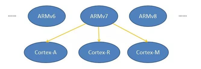
Figure 1 Cortex series under ARMv7
Style A: high-performance processor-level platform, performance comparable to the computer.
Style R: Positioning for high-end embedded systems, high reliability and timeliness.
Style M: ​​For deep embedded, custom embedded systems.
It is worth noting that the processor under Cortex-M does not have a memory management unit MMU.
Second, the memory management unit MMU
The memory management unit is abbreviated as MMU. It is responsible for the mapping of virtual addresses to physical addresses and provides memory access authority checks for hardware mechanisms. In a multi-user, multi-process operating system, the MMU allows individual user processes to have independent address spaces.
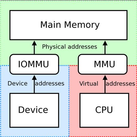
Figure 2 MMU's status
Any microcontroller has a set of addresses that a program can generate, called the virtual address range. Take 32 as an example. The virtual address range is 0~0xFFFFFFFF (4G). When the controller addresses a 256M memory, its available address range is limited to 0x00000000~0x0FFFFFFF (256M). In an MMU-less controller, the virtual address is sent directly to the memory bus to read and write to the physical memory at that address. In the controller with the MMU, the virtual address is first sent to the MMU, mapped to the physical address, and then sent to the memory bus.
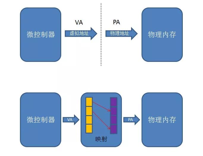
Figure 3 Memory Management Mechanism
Note: The above figure only reflects the memory management mapping mechanism. The concepts of permission mapping, TLB fast tables, and page tables are not discussed in depth.
The main role of virtual memory management is to have a separate address space for each process. The same virtual address in different processes is mapped to different physical addresses by the MMU, and accessing any address in a certain process is impossible to access the data of another process, which causes any process to cause an error instruction or malicious code. The illegal memory access will not accidentally overwrite the data of other processes and will not affect the operation of other processes, thus ensuring the stability of the entire system. On the other hand, each process thinks that it owns the entire virtual address space, so that the implementation of the linker and loader will be relatively easy, regardless of whether the address range of each process is conflicting.
Third, the Linux system
Operating systems are generally divided into real-time operating systems and non-real-time operating systems. Most real-time operating systems are single-process and multi-threaded (multi-tasking). Therefore, address space allocation between threads is not involved, and no MMU is needed, such as VxWorks. The Linux system is a non-real-time operating system, and multi-process is its main feature.
Taking Ubuntu as an example, open a shell and view the address range of the bash process as shown in Figure 4. Its address range is 0x0000000000400000~0xffffffffff600000.
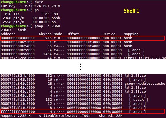
Figure 4 bash address in shell 1
We open another shell to see the address range of the bash process in the shell, as shown in Figure 5. It is not difficult to find that the address range of two different bash processes is exactly the same. In fact, the operating system or the user does not need to consider the physical memory address allocation during the fork() process. This work is done by the memory management unit MMU of the microcontroller.

Figure 5 bash address in shell 2
Since it is a multi-process dependent on the memory management unit, is it only possible to open a process when using embedded Linux? It is definitely not feasible! After booting, even if the user does nothing, visible processes running the system have run dozens to hundreds, as shown in Figure 6.
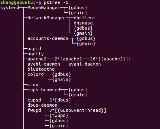
Figure 6 Process Tree
Fourth, summary
Based on the above content, the Linux system has a strong dependence on the memory management unit. If you run Linux on a processor that does not have an MMU, I am afraid that the entire system can only stay in the Uboot stage. Since the Cortex-m processor does not have a memory management unit, it cannot run Linux. Nothing is absolute. If you rewrite the Linux kernel with a sufficiently large memory chip, you can theoretically eliminate the MMU. However, is it worth the workload? In fact, the MMU is created to solve the increasingly complex memory management of the operating system.
Fifth, expand the part
A large number of developers choose to use the embedded Linux system has not played its advantages, just to get the convenience of development, such as Ethernet, 4G cloud, LCD driver, file system, image recognition, python applications and so on. So is there a way to use traditional high-real-time, low-cost microcontrollers without having to face cumbersome hardware-driven development? ZLG’s new AWorks platform, the IoT IoT ecosystem, was born.
D-sub Connector Contacts
A D-sub connector is a form of connector commonly found in electronic and computer systems. It consists of a D shaped metal band and two or more parallel rows of either pin contacts (male) or socket contacts (female). D-sub connector contacts can vary in size, material, current rating, length and resistance.
The most common type of connector is the crimp contact. These are assembled by inserting a stripped wire end into the cavity at the rear of the contact. The cavity is then crushed using a crimp tool, gripping the contact to the wire.
What are D-sub connector contacts used for?
The D-sub connector contacts carry the signal from the source to the destination across the D–sub connection.
Types of D-sub connector contacts
Most D-sub connectors are supplied with contacts ready in place. Contacts can be replaced if damaged or if the application of the D-sub connector is to be changed from the original design specification.
High-current, high-voltage, or co-axial inserts require larger contacts. The material of the D-sub connector contact can be changed if the robustness or quality of the connection needs to be improved.
D-SUB coaxial contact,D-Sub Connectors Contacts,D-Sub Plug Connectors Contact,D-Sub Receptacle Connectors Contact
ShenZhen Antenk Electronics Co,Ltd , https://www.antenkconn.com