A project was rebuilt, and several stations were added behind the PROFIBUS network. The distance is also very close, which is in line with the limitation of the length of the PROFIBUS network. It also conforms to the installation specifications of the network, and the grounding is also good. After the completion of the construction, the slave station appears irregularly. Drop the situation, the story will take you to analyze the cause of the failure. For ease of analysis, the network in Figure 1 is only a schematic diagram. There are three network segments in total. There is only one CPU. The slave failures occur mostly in the 22 slave devices on the right side of the CPU in segment 1. On-site inspection, found that the network finally used the repeater to separate from the newly added site. Due to the installation space problem, there is another station installed in front of the repeater, then connected to the repeater, and the cable connecting the slave to the repeater. Does not match the original cable, a new one, one is old, the cable order number is actually different, is the problem here? Use the terminating resistor to isolate the site using the new communication cable, and then look at the signal waveform. The reflected signal disappears. The problem is found. After replacing the new line with a redundant old line, the error message rarely appears. I really didn't think that a small cable actually caused the entire network to be unstable. If the characteristic impedance of the communication cable does not match, the communication signal will be reflected. If the communication distance is long, reflection occurs at the end, which is more harmful to communication. Even if the cable parameters are the same, but the manufacturer is different, the characteristic resistance will be deviated. (The manual is marked with an error range of plus or minus 10%, so the maximum deviation is 20%.) If a non-PROFIBUS Association cable is used over a long distance, the communication quality is more difficult to guarantee. The installation in Figure 4 cannot be said to be wrong, but the above should be noted. problem. If there is a real problem at the site, use a repeater at the intersection of the two cables.
0.8mm Pin Header
Antenk 0.8mm Pitch Male Header series is a fine pitch, low profile, single/dual/three/four row, PCB mounted connector set intended for limited space applications or where total weight is a factor. Our specially tooled insulators and contacts maintain consistent high quality through our automated production processes. Each series is available in thru-hole PCB or SMT mounting and plated tin, gold or selective gold as specified.
0.8mm Pin Header Options
Number of Rows
0.8mm Pin Header Specifications:
Material: Standard Hi-Temp insulator: Nylon 6T, rated UL94V-0
Pin Header,0.8Mm Male Header,0.8Mm Pin Header,0.8Mm Male Header Pins,0.8mm Pitch Pin Header,SMT 0.8mm Pin Header, THT 0.8mm Pin Header ShenZhen Antenk Electronics Co,Ltd , https://www.pcbsocket.com
The fieldbus network is more complicated, and several network segments are divided. The network topology map is simply drawn according to the field test, as shown in Figure 1. 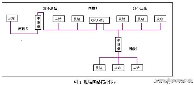
Since PROFIBUS communication is a voltage differential signal, the network segment where the fault occurs is only the result and cannot determine the source of the fault. First use the Amprolyzer (PROFIBUS packet test software, which can be downloaded from the Siemens website) software to test the entire network and find that there are packet errors. The most troublesome thing about on-site debugging is the network consisting of multiple network segments, which must be measured separately. The method of checking is also very simple, which is the elimination method. First, the network is split, the network segment 2 is shielded, and the terminal resistors on the CPU are used to separate the 36 slaves on the left side of the CPU, so that mutual interference between the network segments can be eliminated. Finally, a large number of error messages were found to be sent by the 22 slave devices on the right side of the CPU, thus determining the faulty network segment.
First check the grounding. The surface is well grounded. Because the grounding resistance and grounding line distribution are not taken into consideration, these problems are impossible for temporary debugging on site, so even if the grounding is good.
Secondly, check whether it conforms to the PROFIBUS installation specification, including the distance between the stations, whether there is a branch, etc. After reading for a long time, the reason is not found, even if it is no problem, because it is also unrealistic to check whether each connector is virtual. There is no problem, the site knows that the network segment of 22 slave devices on the right side of the CPU has been modified, new devices have been added, one site has been added to the original network segment, and a repeater has been added for expansion and isolation. I have not found any problems, so where is the problem?
The surface is not visible. You can only view the physical signals of the communication through the oscilloscope, such as whether it is subject to signal interference and PROFIBUS installation problems. The waveforms viewed by the oscilloscope are shown in Figure 2. 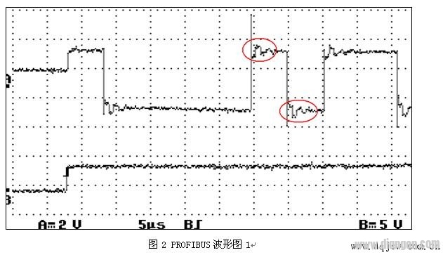
Obvious signal reflection can be seen on the waveform. Through the relationship between time and signal transmission speed, the position of the reflection is calculated to be more than 70 meters away from the main station, and 70 meters is the location where the new equipment is added, and then the site is re-examined. A strange installation phenomenon was found, as shown in Figure 3. 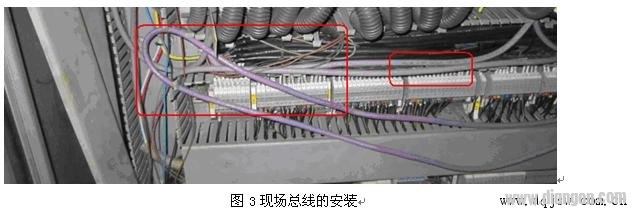

1/Single
2/Double
3/Three
4/Quad
Number of Positions
2 Position
3 Position
4 Position
5 Position
6 Position
8 Position
10 Position
12 Position
14 Position
15 Position
16 Position
17 Position
20 Position
Termination Style
SMD/SMT
Through Hole
Mounting Angle
Right Angle
Straight
Insulator Color: Black
Contacts: Phosphor Bronze
Plating:
U = Gold over nickel underplate
SG = Gold over nickel underplate on
contact area, tin over copper underplate on tails.
T = Tin over copper underplate overall.
Electrical:
Operating voltage: 250V AC max.
Current rating: 1 Amp max
Contact resistance: 20 mΩ max. initial
Insulation resistance: 5000 MΩ min.
Dielectric withstanding voltage: 1000V AC for 1 minute
Mechanical:
Mating durability: 500 cycles min.
Temperature Ratings: Operating temperature: -40°C to +105°C
Max process temp: 230°C for 30 ~ 60 seconds (260°C for 10 seconds)
Soldering process temperature: 260°C
Packaging:
Anti-ESD plastic bags or tubes
Approvals and Certifications:
UL Recognized File no. E224053