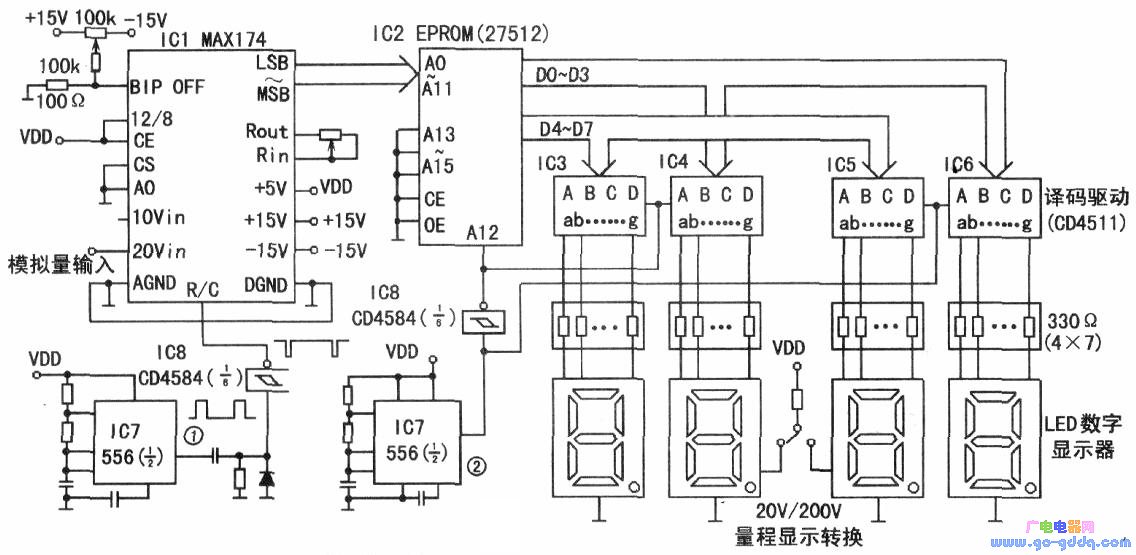
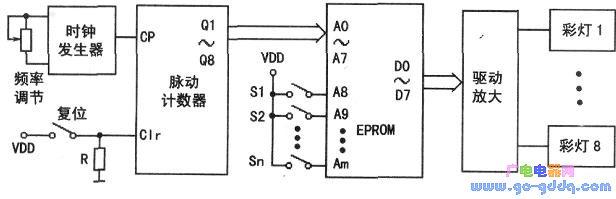
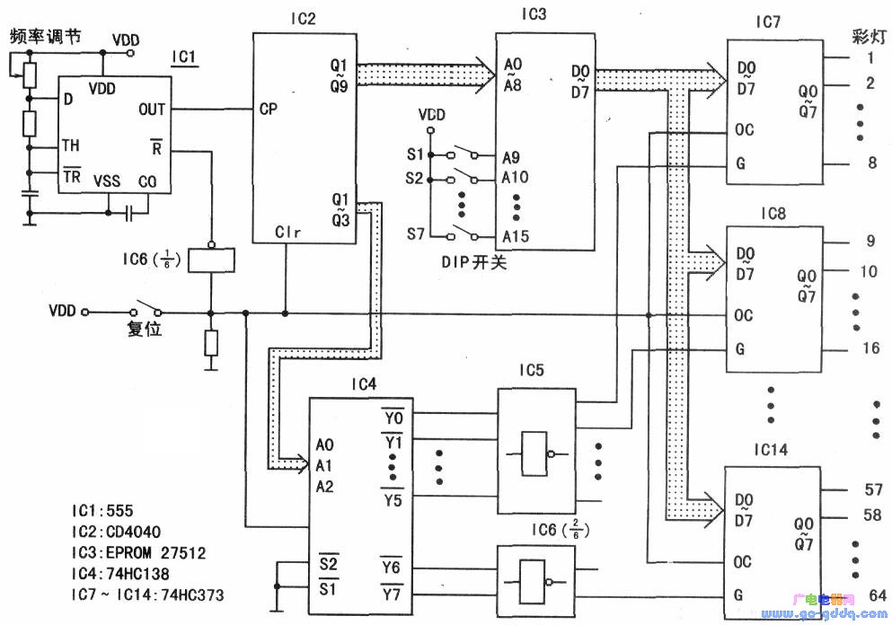
EPROM is a commonly used memory that is commonly used as a program memory in microcontroller development applications. In fact, it is also a programmable logic device (PLD), in addition to its use to implement logic functions, it can also be used to achieve some complex measurement and control. Below are two application examples. High precision digital DC voltmeter The usual digital voltmeter uses a liquid crystal display, the display brightness is not high, and the displayed number is not large. Here we introduce a large display LED digital DC voltmeter with A/D converter and EPROM as the core. It is suitable for applications such as teaching demonstrations and instrument panel cabinets for measuring and controlling equipment. The circuit composition circuit is as shown in the figure above. IC1 is MAX174, IC2 is EPROM27512, IC3~IC6 are BCD code seven-segment display decoding driver, IC7 is dual-time base integrated circuit 556, IC8 is Schmitt trigger CD4584. The four LED digital displays can be integrated with LED devices or LEDs, that is, multiple LEDs are connected in series to form a digital pen segment. Seven pen segments can be mounted in the shape of a digital display to form a large digital display. Meet special requirements. The MAX174 converts the analog input voltage signal into a 12-bit digital signal that is output in parallel as an address signal for the EPROM. IC7 is a 556 dual time base chip, one of which is used to generate A/D conversion start pulse (R/C). At this time, the output 1 of the dual time base chip is processed by the differential circuit and then passed through the Schmitt trigger ( 4584) Forming a sharp pulse. The frequency of this pulse can be set to about 2 Hz. The EPROM stores display data corresponding to the digital quantity obtained by A/D conversion. The digital quantity obtained by each A/D conversion is converted into a four-digit decimal number, the upper two bits of data are stored in the address of 0×××H, and the lower two bits of data are stored in the address of 1×××H (see Above table). IC7 generates an approximate square wave pulse output 2 with a frequency higher than 100 Hz. In the high level phase of pulse 2, the LE terminals of the address terminals A12, IC3, and IC4 of the EPROM are all low level. At this time, the address is 0×××H. The data in the high-level LED is displayed; in the low-level phase of the pulse 2, the address terminal A12 of the EPROM is at a high level, and the LE end of the IC5 and IC6 is at a low level. At this time, the address is 1×××H. The data in the middle is displayed in the lower two LEDs. In this way, the four-bit data is divided into two groups and displayed on the LEDs in one cycle of the IC7 output pulse 2, respectively. When the upper two LEDs are displayed (its LE=0), the lower two LEDs are not displayed (dark) because their LE=1; conversely, when the lower two LEDs are displayed, the upper two LEDs are not displayed (dark ). In order not to cause such a discontinuous display to produce a flickering effect, the frequency of the output pulse 2 of IC7 should be at least not lower than the visual response frequency of the human eye (about 12 Hz). In fact, this frequency can be set to be higher than 12Hz, such as 100 to 1000Hz. Memory Programming The input of the MAX174 is always 0 to +20V. Since the 12-bit output is used, the digital output of the full-scale output is FFFH (=4095). Resolution = 20V / 4096 = 4.88mV / lLSB. However, since the display only takes two decimal places, the display allows the resolution to be 0.01V, so the data in the EPROM only needs to be accurate to two decimal places. The EPROM data is listed in the table above. It should be noted that due to the large amount of data, when compiling data and writing to EPROM, it is better to write a separate program to accomplish this task. Function expansion The above design is a 0 to +20V single-range voltmeter. If you want to expand the range, the method is very simple, just add a switch at the +20V analog input (a double-double-throw switch, one for analog input switching, the other for second LED and The decimal point (DP) switching of the three LEDs can increase the analog input of another 0~+200VDC. Note, however, that the +20Vin input only allows inputs that do not exceed +20V, and the +200V input adds an attenuation that is attenuated to one-tenth (ie, no more than +20V). When the analog input is 0~+20V, the third decimal point DP3 of the LED is lit. When the analog input is 0~+200V, the second decimal point DP2 of the LED is illuminated. Thus, the data stored in the EPROM address is a digital quantity corresponding to the analog quantity of 0 to +20V. There is no need to set two sets of data. If you set the 0 to +10V range measurement (using the +l0Vin input), you can improve the accuracy. The resolution will reach 0.001V. However, you need to write another piece of data in the EPROM. If you want to design more input ranges, you can use the high-order address of EPROM, such as A13, A14 to switch the range. Store different ranges of data in different EPROM address segments. Due to space limitations, it will not be detailed here. Lantern controller In order to add a festive atmosphere to the festival, a large-scale lantern is needed. The following describes a circuit for controlling a lantern using an EPROM memory. The eight-way lantern control circuit is shown in the figure above, and the clock generator provides a clock signal CP for the ripple counter. The clock generator can be used with a 555 time base circuit. The pulsation counter can be a 12-stage pulsation counter circuit 4040, such as a CD4040B. The output of the counter Ql~Q8 is connected to the address signal terminals A0~A7 of the EPROM memory, and the EPROM can adopt 27 series, such as 27512. The remaining address terminals (A8 to A15) of the EPROM are connected to the DIP switch. With this DIP switch, a variety of Lighting lanterns can be set. The chip select terminal CS of the EPROM and the data output strobe OE are both grounded. The 8-channel output of the EPROM is amplified and connected to the 8-way lantern. There can be more than one lantern per lane, which can be combined into multiple collections by series and parallel. If it is a 220VAC lamp, the output of the EPROM needs to be further processed, such as amplification and then connected to the relay or thyristor device. The output of the ripple counter is changed in the order of natural binary numbers of 0000H → 0001H → 0002H. The speed of change is controlled by the frequency of the clock CP. Generally speaking, this frequency should be a lower value. Specifically, it should be adjusted with the "frequency adjustment" button according to actual requirements. The data stored in the EPROM corresponds to the working condition of the lantern. It can be agreed that if the bit value is 0, the corresponding street light is off, and when the bit value is 1, it indicates that the corresponding road light is on. In the circuit of Fig. 2, if the data in the address ××00H is set to OOH, when the reset switch is pressed (the generated address is ××00H), the corresponding output is 00H, and all the lights are off. As shown in the above figure, when the EPROM uses 27512, a total of 64 KB of memory space is divided into 256 sections, each of which has a capacity of 2 8th power = 256B. Each section stores a lantern program that can store a total of 256 programs, that is, 256 different lantern lighting modes can be preset. Assuming that the pulse frequency is 1 Hz, each program can play 2 to 8 power = 256 seconds, about 4 minutes. After the completion of a lantern program, it will start playing from the beginning (because the pulsation counter is counted by the natural binary system under the pulse excitation, the count is full × × FFH and then returns to × × OOH to continue). To change the lighting mode of the lantern, just change the setting of the DIP switch. If you don't need 256 so many lights to light up, just ground the EPROM high address. For example, if only 16 lights are to be lit, the A8 to All of the 27512EPROM can be connected to the DIP switch, and the A12 to A15 can be grounded. Multi-channel expansion If more than 8 channels of lantern control are required, the control method shown in Figure 3 can be used. This is a 64-channel output control circuit. Of course, more or less than 64 channels of lantern control circuits can also be processed by reference to this method. In the above figure, the output of the EPROM is connected to eight 8D data latch chips 74HC373. Their data latch enable terminals G (eight in total) are controlled by the eight outputs of the 3/8 line decoder chip 74HC138 (and inverted by the inverter 74HC04 chip). The address inputs A0 to A2 of the 74HC138 are respectively connected to the outputs Q1 to Q3 of the frequency divider 4040 chip. The data stored in the EPROM is sequentially outputted to the input terminals D0 to D7 of the data latch 373 by the clock CP, and is latched in the corresponding gated 74HC373 chip. When the reset button is pressed, the input address of the EPROM is OOH, and the OC terminal of all 74HC373 chips is low level, all 64 outputs are 0, and no color light is on. In the first clock cycle after reset, 4040 outputs 00000000, that is, Q3Q2Ql=000, that is, the address input of 74HC138 is 000, and the inverse of YO is strobed. That is, IC7 is strobed. The data of the address ××00H in the EPROM is latched to the IC7. In the second clock cycle, 4040 outputs 00000001, that is, Q3Q2Ql=001, that is, the address input of 74HC138 is 001, which can be strobed. That is, IC8 is strobed. The data of the address ××01H in the EPROM is latched to the IC8. ..., in 8 clock cycles, 4040 outputs 00000111, that is, Q3Q2Q1=111, that is, the address input of 74HC138 is 111, and the inverse of Y7 is strobed. That is, IC14 is strobed. The data of the address ××07H in the EPROM is latched to the IC 14. In the ninth clock cycle, 4040 outputs 00001000, that is, Q3Q2Ql=000, that is, the address input of 74HC138 is 000, and the inverse of YO is strobed. That is, IC7 is escaping. The data of address XX08H in the EPROM is latched to IC7. .... It can be seen that the data of 8 consecutive address units in the EPROM can be sent to the 64 color control terminals in bits (BIT) every 8 clock cycles. (Note: These 8 consecutive address units should be ×××0~×××7H or ×××8~×××FH, and within these 8 clock cycles, the data of the uncontrolled color control terminal is Keep it.) If the following data is stored in the EPROM, "lighting up the 1N64# lantern" can be realized: (assuming that the control DIP switch of this lighting mode is grounded, that is, the high-order address input is 0). The address OOOOH stores 01H, 0001-0007H. 00H is stored in the medium; 02H is stored in the address 0008H, OOH is stored in the 0009-000FH; 04H is stored in the address 0010H, and 00H is stored in the 0011 to 0017H; ...; 80H is stored in the address OIF8H, and OOH is stored in 01F9 to 1FFH. There are 512 address units listed above, and manual writing will be very cumbersome. It is much easier to programmatically generate the data to be stored by each address unit and write it to the E-PROM. SHENZHEN CHONDEKUAI TECHNOLOGY CO.LTD , https://www.szsiheyi.com