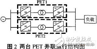
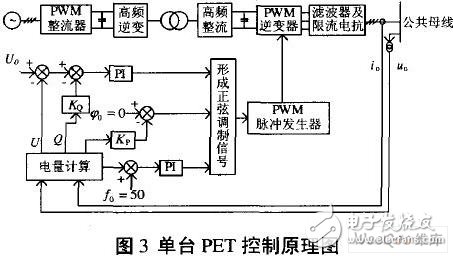
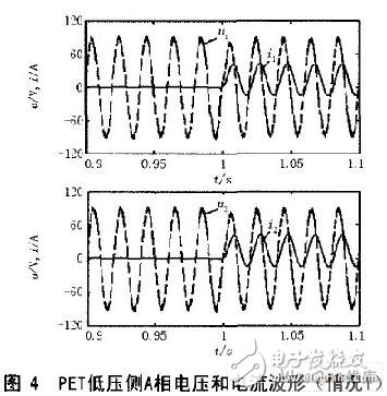
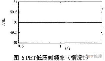
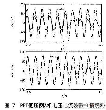
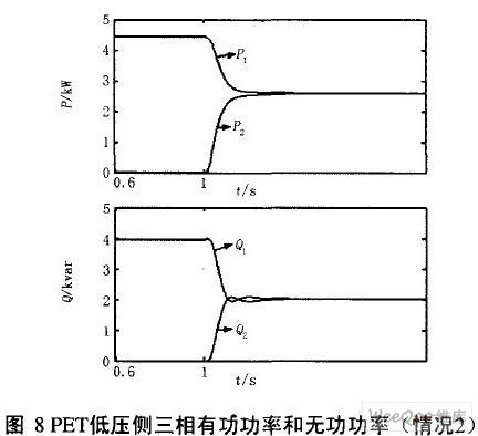
Parallel operation of power electronic transformers is conducive to further improving the power supply reliability and power supply capacity of the power system, and has important research value. In order to realize the stable and reasonable load distribution among the power electronic transformers operating in parallel, and have good dynamic response characteristics, the control strategy and model of the power electronic transformer are established based on the active and reactive power adjustment characteristic equations, and the Matlab/Simulink model is used to compare the two The simulation results show that the control strategy can realize the stable and reasonable distribution of active load and reactive load between power electronic transformers in parallel operation under the premise of maintaining the rated power supply frequency. And the dynamic characteristics are good. 0 Preface Power-Electronic Transformer PET (Power-Electronic Transformer), as a new type of power transformer, has attracted more and more attention from researchers at home and abroad. It is a substation that contains power electronic converters and realizes magnetic coupling through high-frequency transformers. PET not only completes the transformation, isolation and energy transfer of conventional transformers, but also functions as a power quality controller. It is a new, multi-functional transformer. Using it in the power distribution system can not only reduce the voltage but also ensure the power quality [1]. Parallel operation of two or more PETs is an important operation mode of transformers, which has important research value. However, the current domestic and foreign researches on PET mainly focus on its topology and control strategy, and the research on its application in power system and its operating characteristics is relatively weak. Literature [2] uses a master-slave control scheme to solve the parallel current sharing problem on the AC side of the parallel PET output; Literature [3] simulates the dynamic process of the parallel PET load with a step change and a nonlinear load. This paper studies the control strategy of parallel PET load distribution for power distribution, and conducts dynamic simulation of typical operations [2,3]. 1 Basic structure and control strategy of PET The basic topological structure of PET is divided into AC-AC-AC converter and AC-DC-AC-DC-AC dual-DC converter. The former has a simple structure, but the controllability is not high: the latter has a complex structure, a complete control strategy and strong practicability. A typical AC-DC-AC-DC-AC dual-DC topology is shown in Figure 1. The voltage-type PWM rectifier circuit of the PET primary side adopts decoupling voltage and current double closed-loop control. Regardless of whether the load of the transformer is inductive or capacitive, as long as the power factor of the grid is within a certain range, the power factor of the grid can be close to 1; The single-phase inverter circuit realizes high-frequency inverter, and only needs to adopt open-loop control. In order to reduce the size and weight of the transformer, the magnetic material of the transformer adopts high magnetic core such as ferrite. The secondary side rectifier circuit of the transformer is used to realize high frequency rectification, and the two-way flow of energy is not considered for the distribution transformer, so it uses an uncontrolled rectification circuit. In order to output constant voltage and constant frequency AC voltage, the PET secondary side inverter circuit adopts voltage closed loop control [4]. 2 PET parallel operation control principle Parallel operation of two or more PETs is an effective way to improve the reliability of the system and expand the capacity. Research on the parallel operation of PET is not deep enough. The working principle of the PET secondary inverter is the same as that of the US inverter, and the parallel operation of multiple UPSs has relatively rich results [5-7], which can be used for reference when studying the parallel problem of PET. The currently proposed PET parallel control methods mainly include: centralized control mode, master-slave control mode, distributed logic control mode and no interconnection line control mode [2]. This article mainly focuses on the parallel operation of two PET without interconnection. Figure 2 is a structural diagram of two PET parallel systems, the original side of which is connected to the same common bus. In order to avoid circulating current in parallel transformers, the frequency, amplitude, and phase of the secondary side voltage of each PET must be consistent; in order to realize the stable distribution of active load and reactive load between parallel transformers, each PET should have active power adjustment Characteristics and reactive power adjustment characteristics. The control structure diagram of the PET secondary inverter with differential adjustment characteristics is shown in Figure 3. The frequency, amplitude and phase of the PET secondary voltage depend on the sinusoidal modulation signal of the PWM pulse of the inverter. The characteristics of the sinusoidal modulation signal are related to the given frequency f0, the given phase Ï0 and the given amplitude. Take f0=50Hz to ensure the rated frequency. Ï0 corresponds to the initial phase angle of the voltage when the active load is P0 (usually taken as 0, and the active compensation coefficient Kp>0 is introduced), then the active power adjustment characteristic can be formed Ï=Ï0-KpP (1) U0 corresponds to the voltage amplitude when the reactive power load Q=0, and the reactive power compensation coefficient KQ>0 is introduced to form the reactive power difference characteristic U=U0-KQQ (2) For each PET running in parallel, the values ​​of Ï0 and U0 should be the same. Due to the introduction of active and reactive power compensation, when the load changes, each PET running in parallel will automatically adjust the phase angle and amplitude of its output voltage, and automatically realize the transformer In order to distribute the load reasonably according to the capacity of the transformer, the standard unit values ​​of Kp and KQ of each PET based on its own capacity should be equal, generally 0.01-0.05. Literature [2,8] proposes to use frequency difference characteristics to distribute the active power of parallel PET and inverter power supply. Obviously, in this control mode, the power supply frequency cannot be maintained at 50Hz under different loads; and in order to ensure the frequency quality, the value of the frequency adjustment coefficient must be small, which is not conducive to the stable distribution of active loads between parallel PETs. In contrast, the initial phase angle adjustment characteristics adopted in this article can maintain constant frequency power supply, and can select reasonable adjustment coefficients according to needs to achieve a stable and reasonable distribution of active loads. The output voltage frequency of each PET participating in parallel must be equal to 50 Hz to ensure normal operation. In Figure 3, this can be done due to the closed-loop PI control of the frequency. The parameters of the PET in parallel operation may not be exactly the same. The most common ones are the different inductance parameters of the current-limiting reactor or the connecting line. The voltage measurement points in Figure 3 are deliberately set on the common bus, even if the PET parameters are inconsistent, it can ensure the stable and reasonable distribution of power between the parallel PETs. If the voltage measurement point is located at each PET output terminal, this cannot be guaranteed [3]. 3 Simulation analysis This paper uses Matlab6.5/Simulink to build a simulation model to simulate the parallel operation of two PETs with the same parameters. The main parameters of the system are: PET rated capacity 10kVA, rated voltage 240/110V; PET2 rated capacity 10kVA, rated voltage 240/110V, system frequency 50Hz, high-frequency transformer frequency 1000Hz, IGBT switching frequency 9000Hz; KP, KQ selenium are both standard unit values 0.01, the frequency setting value f0 is 50Hz, the phase setting value Ï0 is 0, and the amplitude setting value U0 is the unit value of 1.0. 3.1 Two PETs are put into parallel operation at the same time (case 1) At 1.0s, two PETs are put into parallel operation from no-load on the low-voltage side, and assume a comprehensive load with a power factor of 0.8. The relevant variable waveforms are shown in Figure 4-6. It can be seen from the figure that the waveforms of the corresponding variables of the two PETs are the same. After parallel operation, the load currents assumed are equal, which realizes current-sharing control and stable distribution of active and reactive loads, and the frequency remains constant. 3.2 PET2 joins parallel operation (case 2) PET1 is running with load, and PET2 is put in no-load state at 1.0s, and two PETs are running in parallel. The relevant waveforms are shown in Figure 7 and Figure 8. It can be seen from the figure that after PET1 is switched from stand-alone operation to parallel operation, the load current, active and reactive load it undertakes are reduced, and the decline is borne by PET2, and finally the current sharing between the two parallel PETs is realized. Control and stable distribution of active and reactive loads with good dynamic response performance. 4 Conclusion In this paper, the PET control strategy and model are established based on the active and reactive power differential characteristic equations. Based on the model, the dynamic process of PET parallel operation is simulated. The simulation results show that the control strategy can realize the stable distribution of active and reactive loads on the premise of maintaining the rated power supply frequency, and the dynamic characteristics are good. Nintendo WII U Console Adapter This WII Uadapter is factory supply with cheap price and high quality, we provide US EU UK Plug, for the UK plug, we also can do fused plug to protect your charger better.
Nintendo WII U Adapter, Nintendo WII U Console Charger, Nintendo WII U Adaptor, Nintendo WIIU AC Charger, Nintendo WII U Power Supply Shenzhen GEME electronics Co,.Ltd , https://www.gemesz.com

Product Features:
➤ Top quality replacement power adapter for Nintendo Wii U Console(With automatic voltage function)
➤Output: 15V 5A;Simple plug and play setup, allow you to charge and play at the same time from up to 7 ft away.
➤ It supports to use both AC 110V and AC 220V, which avoids the defect of using AC 110V only with original Nintendo adapter.
Product Specifications:
- Color: Grey
- Input: AC 100-240V
- Output: DC 15V5A


- Cable Length: Approximate 90cm (Wall plug side to AC adapter), Approximate 100cm (Console side to AC adapter)