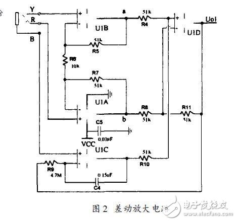
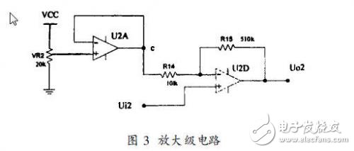
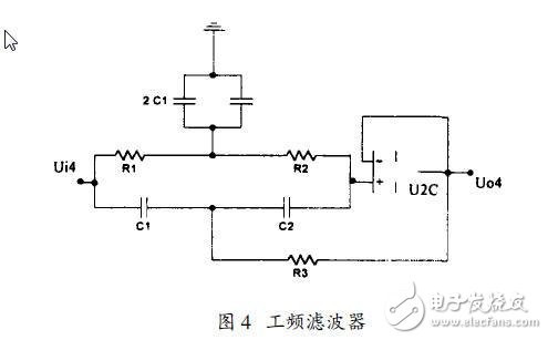
The monitor is a device or system used to measure and monitor the physiological parameters of the patient, compare it with the known set value, and issue an alarm if there is an out-of-tolerance. The portable monitor is small and convenient, simple in structure, stable in performance, can be carried around, can be powered by batteries, and is generally used for monitoring in non-care rooms and out-of-care patients. The lead system uses a general three-electrode method, the right upper chest electrode and the left lower abdomen electrode are ECG sampling electrodes, and the right lower abdomen electrode is the right leg drive electrode. This connection method is effective and practical, which is conducive to portable use. The analysis and processing system of the portable monitor can be divided into two parts, one is a pocket monitor carried on the examinee, and the other is an electrocardiogram processing and diagnosis system composed of a microcomputer system. The examinee records the dynamic ECG signal of a certain period of time by the monitor, and transmits the data to the hospital's ECG processing and diagnosis system through GPRS communication. The frequency of the body surface ECG signal is mainly concentrated in 0.05~100Hz, and the amplitude is 10μV~4mV (typical value is 1mV), which is a weak bipolar signal with low frequency. It is drowned in a lot of strong interference and noise. These interferences mainly include internal interference signals such as myoelectric signals and respiratory wave signals, and the effects of external electromagnetic field interference signals, which are mainly 50Hz power frequency interference and noise between the electrode and the skin interface. Therefore, to accurately measure the ECG signal, an amplifier with excellent performance must be designed. The core and key of the amplifier is the design of the pre-stage. The entire pre-stage circuit is composed of a pre-amplifier circuit and a filter circuit, and its structure is shown in Figure 1. The preamplifier circuit of the portable computer is a key component for automatic detection of cardiac function. It is required that the system can detect the ECG signal through the body surface sensor without distortion under the background of strong noise, amplify it to a suitable amplitude, and send it to A/D becomes a digital signal for computer analysis and processing. According to the characteristics of the ECG signal and the way of extracting through electrodes, the pre-stage should meet the following requirements: (1) High input impedance. The ECG signal extracted by the electrode is a weak signal of an unstable high internal resistance source. In order to reduce the influence of the internal resistance of the signal source, the input impedance of the amplifier must be increased; (2) High common mode rejection ratio CM RR. The power frequency interference carried by the human body and the interference of physiological effects other than the measured parameters are generally common mode interference. The pre-stage adopts a differential amplification form with high CM RR, which can reduce the conversion of common mode interference to differential mode interference; (3) Low noise and low drift; (4) High safety to ensure the absolute safety of the human body. 1. 1 differential amplifier circuit For the ECG signal, the collected signal belongs to the differential mode signal, so the three-op-amp differential amplifier circuit is used as the first-stage amplifier circuit. It has high input impedance (generally up to 109 ohms or more), low bias current, and high Common mode rejection ratio, characteristics of single-ended output. It connects a non-inverting amplifier to each input terminal on the basis of a basic operational amplifier. So the first stage of the differential amplifier circuit is two non-inverting amplifiers (U 1A and U 1B), and the second stage is a differential amplifier (U 1D). The total voltage gain A u is equal to the product of the two-stage gain. Since the first stage adopts in-phase input and has higher input resistance, the balanced and symmetrical structure of the circuit is resistant to the output error voltage caused by common mode rejection ratio, offset and temperature. The second stage differential amplifier circuit converts double-ended input into single-ended output. After cascading the two-stage circuits, they complement each other's strengths, so that the combined circuit has a series of advantages such as high input impedance, convenient voltage gain adjustment, common-mode rejection ratio and drift cancellation. The operational amplifier U 1C is an integrating circuit, and its function is to form a negative feedback circuit together with U 1D to eliminate the influence of baseline changes on the output signal and stabilize the output voltage. Due to the series feedback form, the amplifier circuit has a higher input impedance and reduces the distortion. Calculate the gain of the amplifier as follows: R5= R7= R', R4= R8= R'' Therefore, the total gain of the differential amplifier circuit is: 1.2 Unipolar adjustment circuit The ECG signal is a low-frequency bipolar signal. For a portable computer powered by a battery, the structure is simple, and reducing power consumption is its important feature. To this end, we designed a DC voltage divider circuit to raise the ECG signal to a unipolar signal in the positive level range. In order to make the operational amplifier work in the linear amplification region, we set the DC voltage to half of VCC (3.3V). 1.3 Amplifying stage circuit Because the Ui2 signal is composed of a DC signal and a weak ECG signal. The function of the second-stage amplifying circuit is to amplify the ECG signal, while keeping the DC signal in a relatively stable state. For this reason, adjust the position of VR2 so that the voltage of Uc is equal to the DC component of Ui2, and the DC component of Ui2 will not be amplified by U2D. Uo2= U-= Ui2 the gain of the amplifier stage circuit is: It can be obtained that the total gain of the preamplifier circuit is close to 600, which can amplify the millivolt ECG signal to the volt level and be between 0V and 2.5V. For ECG monitoring equipment, the primary criterion for evaluating its overall performance is that the ECG signal has high anti-interference ability without distortion, and is safe and reliable. In order to avoid the influence caused by interference, the most effective measure is to eliminate the interference source. But in actual application, it is impossible to completely eliminate the interference source, so measures must be taken on the hardware circuit to improve the anti-interference of the system. Commonly adopted measures can be divided into two categories: one is to eliminate the channel through which interference enters the system; the other is to weaken the system's sensitivity to interference signals. 2. 1 Improve the input impedance and common mode rejection ratio of the preamplifier The human body is placed in a space full of electromagnetic fields, just like an antenna receiver, the human body induces voltages of various frequencies, and most of the input terminals of the ECG instrument exist in the form of common-mode voltage, of which the strongest is the power line through the distributed capacitance A 50Hz AC voltage coupled to the human body. The suppression of common-mode signals includes improving the common-mode rejection ratio (CM RR) of the preamplifier circuit and improving the symmetry of the electrical characteristics of the circuit, leads, and electrodes to increase the input impedance. By using high-precision, high common-mode rejection ratio integrated op-amp devices to build a three-op-amp differential amplifier circuit, the common-mode rejection ratio can be improved. It is worth noting that the actual common-mode rejection of the amplifier is affected by the electrode system on the front side of the amplifier. When extracting biopotentials through two electrodes, the two equivalent source impedances are generally not equal, and their value is related to the secretion of human sweat glands and the cleanliness of the skin. The skin contact electrode at each electrode is unbalanced and varies from person to person. The harm caused by this imbalance is the conversion of common mode interference to differential mode interference, resulting in the output of common mode interference. For this conversion that has already taken place, no matter how high the common-mode rejection of the amplifier itself is, it will not help. However, increasing the amplifier's input impedance will reduce this conversion. 2.2 Design hardware filters to eliminate high-frequency interference Since the ECG signal is a low-frequency signal, and high-frequency interference is relatively high compared to the ECG signal, the low-frequency cut-off frequency can be selected in a relatively wide range. The low-pass cut-off frequency of a general electrocardiograph or monitor is 90 ~ 120Hz. Taking into account the simple structure of the portable machine, the design of the low-pass filter adopts a first-order filter circuit. The software filtering introduced later will also be used to eliminate high-frequency interference. 2. 3 design hardware filter to eliminate power frequency interference Power frequency interference is a common mode signal, and it has a particularly strong interference to the ECG signal. Therefore, it must be suppressed from both analog and digital aspects. The elimination of power frequency interference can be achieved with a second-order voltage-controlled voltage source band-stop filter in the analog circuit. The parameters are selected as follows:
What is a miniature slip ring? Miniature slip rings are rotary electrical connectors that allow power and data to be transferred between a stationary and rotating structure. They are often used in medical, military, and aerospace applications where size and weight are critical factors.
A miniature slip ring typically consists of two parts: a stationary housing and a rotating contact assembly. The contact assembly contains the brushes that make electrical contact with the rotating structure, as well as the rings that conduct current or data.
The housing can be made from any number of materials, including metals, plastics, and composites. It is typically designed to be as small and lightweight as possible while still providing adequate strength and durability.
The contact assembly is made from precious metals such as gold or silver in order to provide good electrical conductivity.
Technology improves with the continuous development of precision machinery. The more sophisticated the equipment, the smaller the volume will be. And the space that can be accommodated for installing the slip ring is also very small. The key parts of some equipment are quite a district. Especially in the high-end military, aerospace and aviation fields. 360-degree rotation is required to transmit current and signals. And the installation space is greatly reduced. It is to make the equipment work more smoothly. Therefore, it is necessary to design the slip ring to be small and exquisite. Otherwise, it won't meet the needs of the installation.
Miniature Slip Ring,Slip Ring Parts,Slip Ring Type Induction Motor,Slip Ring Rotor Dongguan Oubaibo Technology Co., Ltd. , https://www.sliprob.com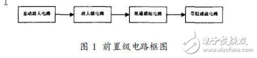

At the same time, we have moved with the continuous development of science and technology. Various high-end precision instruments have been developed. It requires the slip ring to transmit the current amount of general power. Also often undertake the transmission of weak electrical signals and various weak signals. The transmission medium is wider, and the number of loops of the slip ring is increasing.
