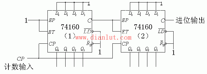
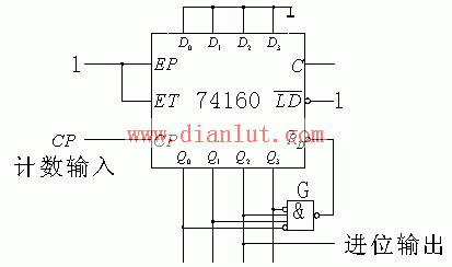
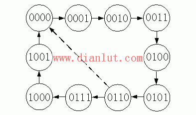
Here are two examples of counter application circuits. In these two examples, we use a synchronous decimal addition counter 74LS160 to form a hex counter and an octal counter. In addition to the counting function, the counter product has some additional functions, such as asynchronous reset, preset number (note that there are two types of synchronous presets and asynchronous presets. The former is controlled by the clock pulse, the latter is not controlled by the clock pulse) Keep (note that there are two ways to keep the carry and not to keep the carry). Although the counter products are generally only binary and decimal, with these additional functions, we can easily use the counters we can get to form an arbitrary number of counters. Since the hex counter has six valid states and the decimal counter has ten valid states, when using a decimal counter to form a hex counter, we only need to keep the six states of the decimal counter. The ten valid states of the 74LS160 are BCD encoded, namely 0000, 0001, 0010, 0011, 0100, 0101, 0110, 0111, 1000, 1001 [Fig. 5-1]. Figure 5-1 Which six states do we keep? In theory, we can keep which six states. However, in order to make the circuit the easiest, it is still a bit more important to keep which six states. In general, we always keep two states 0000 and 1001. Since the 74LS160 changes from 1001 to 0000, a carry pulse will be generated at the carry output, so after we have reserved the two states 0000 and 1001, we can use the carry output of the 74LS160 as the carry output of the hex counter. It is. Thus, the state loop of the hex counter can be 0000, 0001, 0010, 0011, 0100, and 1001, or 0000, 0101, 0110, 0111, 1000, and 1001. We may wish to adopt the six states of 0000, 0001, 0010, 0011, 0100 and 1001. How to make the 74LS160 jump from the 0100 state to the 1001 state? We use a mixed logic NAND gate to form a decoder [Fig.5.3.37b]. When the state of the 74LS160 is 0100, the NAND gate outputs a low level, which is low. The level causes the 74LS160 to operate in the preset number state, when the next clock pulse arrives, due to Figure 5.3.37b Connect the 74160 into a hexadecimal counter (set to 1001) using the set method A little more cumbersome than this solution is the use of the asynchronous reset terminal of the 74LS160. In the following circuit [Fig. 5.3.44], there is also a decoder composed of mixed logic NAND gates. Figure 5.3.44 Connecting the 74LS160 to a hex counter using the zeroing method However, this decoder outputs a low level when the input is 0110, so that the 74LS160 is asynchronously reset and enters the state of 0000. Starting from the 0000 state, as the clock pulse continues to arrive, the 74LS160 changes to the 0001, 0010, 0011, 0100, 0101, and 0110 states in sequence [Fig. 5-2]. Some people may say: "No! This circuit has a total of seven states, it should be a hexadecimal counter!" We said that although this circuit has to go through seven states, it only takes six pulses to complete a counting cycle, so it Still a hex counter. Figure 5-2 Let's analyze it carefully. Assume that the initial state of the 74LS160 is 0000. After the first clock pulse arrives, its state becomes 0001. After the second clock pulse arrives, its state becomes 0010, ..., after the fifth clock pulse arrives, it The state changes to 0101, and after the sixth clock pulse arrives, its state changes to 0110. When 74LS160 is in the state of 0110, the decoder outputs a low level, which causes the 74LS160 to be asynchronously reset and enters the state of 0000. In this passage, "asynchronous reset" is a keyword. Unlike synchronous resets, asynchronous resets are not controlled by clock pulses. Thus, the output of the decoder just goes low, and the state of 74LS160 becomes 0000. Ideally, the 74LS160 will first stay in the 0110 state for a while in the sixth clock cycle and then stay in the 0000 state steadily. We know that the counter works on clock pulses. Counting is the number of clock pulses. In our example, the 74LS160 starts from the 0000 state and returns to the 0000 state after six (instead of seven) clock cycles, that is, every six (instead of seven) clock pulses cycle the 74LS160 state. once. Therefore, this circuit is a hex counter. The counting cycle includes six stable states of 0000, 0001, 0010, 0011, 0100, and 0101. Some people may say, "Hey, listen to you for this explanation. I also think it is a hex counter. However, counting seven states into six is ​​always a bit awkward. Oh, as long as it works, I don't care. It is going through six states or seven states." I said: "Yes, I think so. However, things are counterproductive! If you don't improve, this circuit really can't work." Why? We know that the state of the counter is remembered by the trigger. 74LS160 has four triggers Figure 5.3.36 Figure 5.3.34 Circuit Improvement Two NAND gates form the RS latch to its The second example requires us to form an hex counter, that is, the state of the counter is 0010 to 9910. Since 100 is equal to 10 times 10, we can use two 74LS160 to form an octal counter, where the state of one counter represents a single digit, the state of the other counter represents a tens digit, and the latter is the carry signal of the former. Control the count. We have two options. The first scheme is called the parallel travel mode [Fig. 5.3.3]. Figure 5.3.39 Example 5.3.3 circuit parallel travel mode The characteristic of this scheme is that the CP terminals of the two 74LS160s are connected to the clock pulse. However, the first 74LS160 always works in the counting mode, and each clock pulse changes its state; the first 74LS160 only works in the counting mode when the first 74LS160 carry output is high, every ten clocks. The pulse changes its state. If the counter starts counting from the 0010 state, after the ninth clock pulse arrives, the state of the first 74LS160 becomes 910 and the carry output goes high, causing the second 74LS160 to enter the counting mode. Because the second 74LS160 enters the counting mode later than the ninth clock pulse arrives, that is, the second 74LS160 has not entered the counting mode when the ninth clock pulse arrives, so the ninth clock pulse does not The state of the second 74LS160 changes and its state is still 010. Thus, the state of the counter is 0910. After the tenth clock pulse arrives, the state of the first 74LS160 changes to 010 and the carry output goes low, causing the second 74LS160 to exit the counting mode. Because the second 74LS160 exits the counting mode later than the tenth clock pulse arrives, that is, the second 74LS160 has not exited the counting mode when the tenth clock pulse arrives, so the tenth clock pulse makes the second The state of the 74LS160 changes and its state changes to 110. Thus, the state of the counter is 1010. The second option is called serial carry mode. The feature of this scheme is that both 74LS160s always work in the counting mode. However, the CP end of the first 74LS160 is connected to the clock pulse, and each clock pulse changes its state; the CP end of the first 74LS160 is connected to the first 74LS160 carry output, which is made every ten clock pulses. Its status has changed. Students often ask: "Why do you have a NOT gate between the carry output of the first 74LS160 and the clock input of the second 74LS160?" This is a bit of a mystery. If the counter starts counting from the 0010 state, after the ninth clock pulse arrives, the state of the first 74LS160 becomes 910 and the carry output goes high. If there is no such gate, the level change of the first 74LS160's carry output will change the state of the second 74LS160 and its state will change to 110. So the state of the counter changes from 0810 to 1910 instead of the 0910 we want. With this NOT gate, the situation is different, because the rising edge of the first 74LS160's carry output is converted to a falling edge by the NOT gate, so the level change of the first 74LS160's carry output does not make the second The state of the 74LS160 changes and its state is still 010. Then the state of the counter changes from 0810 to the 0910 we want. After the tenth clock pulse arrives, the state of the first 74LS160 changes to 010 and the carry output goes low. Because the falling edge of the first 74LS160's carry output is converted to a rising edge by the NAND gate, the level change of the first 74LS160's carry output changes the state of the second 74LS160, and its state changes to 110. Then the state of the counter changes from 0910 to 1010. OLED is organic light-emitting diode (D1de), which has the characteristics of self illumination, high brightness, wide viewing angle, high contrast, flexibility, low energy consumption and so on. Therefore, it has been widely concerned. As a new generation of display mode, it has gradually replaced the traditional liquid crystal display, and is widely used in mobile phone screen, computer display, full-color TV and so on. OLED display technology is different from traditional liquid crystal display technology. It does not need backlight. It uses very thin organic material coating and glass substrate. When there is current passing through, these organic materials will emit light. However, as organic materials are easy to react with water vapor or oxygen, OLED displays have high requirements for packaging. Package Locating OLED Cover Glass,High Precision OLED Cover Glass,Special Desiccant Installed OLED Cover Glass SHAOXING HUALI ELECTRONICS CO., LTD. , https://www.cnsxhuali.com
![]() Equal to 1001, 74LS160 will be preset to 1001, so we have achieved state jumps.
Equal to 1001, 74LS160 will be preset to 1001, so we have achieved state jumps. 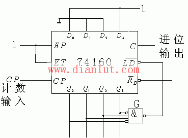
![]() Memory separately
Memory separately ![]() . The speed of these four triggers is different. In the process of 74LS160 changing from 0110 to 0000,
. The speed of these four triggers is different. In the process of 74LS160 changing from 0110 to 0000, ![]() The state of the sum does not change,
The state of the sum does not change, ![]() The state of the sum is changed from 1 to 0. We assume that the ratio is faster, so when it is just changed from 1 to 0, it is still in the 1 state. At this time, the output of the decoder is not low, and the asynchronous reset signal of the 74LS160 disappears. In the case where the asynchronous reset signal duration is too short, the state of 1 will remain unchanged. The 74LS160 will then stay in the 0010 state instead of the 0000 state we expect. Obviously, this is a competitive risk phenomenon, because whether the 74LS160 can change from 0110 to 0000 depends on the competition result. How do I keep the asynchronous reset signal long enough? Let's take a look at this circuit [Figure 5.3.36].
The state of the sum is changed from 1 to 0. We assume that the ratio is faster, so when it is just changed from 1 to 0, it is still in the 1 state. At this time, the output of the decoder is not low, and the asynchronous reset signal of the 74LS160 disappears. In the case where the asynchronous reset signal duration is too short, the state of 1 will remain unchanged. The 74LS160 will then stay in the 0010 state instead of the 0000 state we expect. Obviously, this is a competitive risk phenomenon, because whether the 74LS160 can change from 0110 to 0000 depends on the competition result. How do I keep the asynchronous reset signal long enough? Let's take a look at this circuit [Figure 5.3.36]. 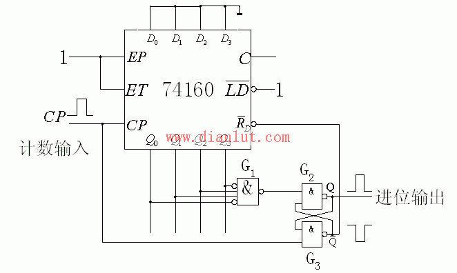
![]() The low level of the terminal output is used as the asynchronous reset signal of the 74LS160. If the 74LS160 starts counting from the 0000 state, the rising edge of the sixth clock pulse arrives at the 0110 state, the RS latch is set, and the terminal outputs a low level. After the 74LS160 pauses for a short time in the 0110 state, it quickly switches to another state, such as 0010 or 0100, and the negative pulse output from the decoder disappears. If we use this narrow pulse directly as the asynchronous reset signal of the 74LS160, the counter does not necessarily work reliably. If we use this narrow pulse as the set signal of the RS latch, use the clock pulse as the reset signal of the RS latch, and then use the RS latch as the asynchronous reset signal of the 74LS160, the counter must be able to work reliably because The width of the output negative pulse is equal to the duration of the clock pulse high level.
The low level of the terminal output is used as the asynchronous reset signal of the 74LS160. If the 74LS160 starts counting from the 0000 state, the rising edge of the sixth clock pulse arrives at the 0110 state, the RS latch is set, and the terminal outputs a low level. After the 74LS160 pauses for a short time in the 0110 state, it quickly switches to another state, such as 0010 or 0100, and the negative pulse output from the decoder disappears. If we use this narrow pulse directly as the asynchronous reset signal of the 74LS160, the counter does not necessarily work reliably. If we use this narrow pulse as the set signal of the RS latch, use the clock pulse as the reset signal of the RS latch, and then use the RS latch as the asynchronous reset signal of the 74LS160, the counter must be able to work reliably because The width of the output negative pulse is equal to the duration of the clock pulse high level. 